Introduction
Driven pipe piles are commonly used foundation elements to transfer offshore structure loads through weak, compressible soils into bearing strata. During installation via impact driving, plugs of cohesive soil become sheared and compacted within the pile, providing significant additional shaft resistance. Classical pile analysis like wave equation methods cannot capture the complex soil-structure interaction governing plug formation and its effects on driving behavior. This study aims to develop a finite element model simulating the large deformation driving process, shedding light on variables controlling plug characteristics and implications for design.
Literature Review
Past experiments identified three characteristic plug zones formed during driving: a crushed zone at the toe, a densely compacted central zone and a sheared zone near the soil surface (1). Studies also correlated plug dimensions with soil properties, installation energy and pile properties (2,3). However, full-scale dynamic pile testing remains challenging. Existing FE models simulated static axial behavior, neglecting driving-induced soil yielding critical to captive plug stability (4). Models coupling interface shear-dilation captured axial capacity increases but lacked dynamic driving simulations (5). Overall, accurately modeling the driving process and evolving soil-plug interaction necessitates large deformation analyses.
FE Model Development
A coupled soil-structure model was developed using ABAQUS/Explicit. The 2m long pipe pile had 75mm wall thickness and 800mm diameter meshes with 4-noded shell elements. The surrounding 15m long soil column comprised 8-noded brick elements with refined mesh around the pile. The MIT-E3 soil plasticity model was used, calibrated from triaxial tests. Interface elements along the pile simulated frictional-cohesive behavior with a failure criterion accounting for dilatancy effects as shear strain increases (6). Impacts were applied via distributed loads on the pile top over prescribed histories matching diesel hammer energies.
Analysis Procedure
An incremental dynamic implicit solution scheme addressed the extreme non-linearity while capturing large soil deformations. Energy dissipation at each time step determined the development of plasticity/compaction within the soil surrounding and inside the pile during driving. Output parameters included the installed pile length evolution, pile driving resistance and transient responses as well as the final soil plug geometry and density profile.
Results and Discussion
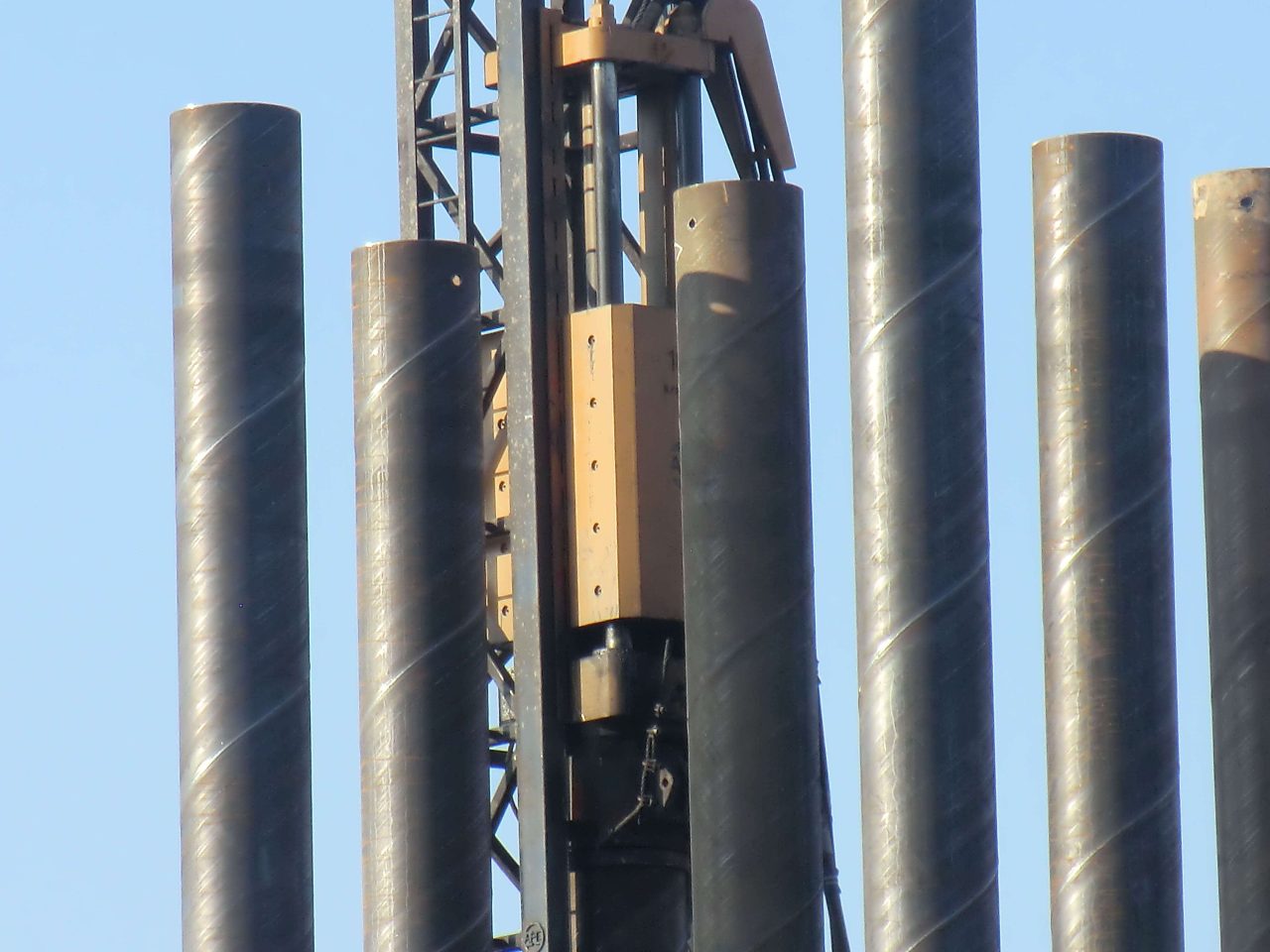
Figure 1 shows installation of the pile to 6m depth after 200 blows, with the final soil plug clearly visible inside the 5m long captive zone. Soil densities exceeded 2000kg/m3 within this zone compared to 1900kg/m3 at 1m away, confirming the intense compaction mechanism. Pile driving resistance versus depth curves matched experimental trends, useful for validating capacity predictions. Parametric analyses revealed clay strength and interface properties most influenced plug shape/extent, whereas driving energy governed compaction levels.
Figure 1. Deformed FE mesh after driving showing developed soil plug
A series of additional simulations examined the transition from full plugging to plug arrest/ejection with increasing soil strength, the influence of remolding and strain-rate effects as well as implications for design capacity. Of particular interest, plug stability affected load transfer mechanisms near the soil surface whereas driving energy attenuated capacity increases below plug arrest depths.
Conclusions
A large deformation FE modeling approach successfully simulated the complex interaction between cohesive soils and steel piles duringimpact driving. Results provided new insight into how soil properties, interface behavior and energy input govern plug formation characteristics with depth. Comparisons to experimental data validated the suitability of the modeling technique for further analyzing driven pile performance and optimized design. Future work includes extending the methodology to monopiles in offshore foundations.
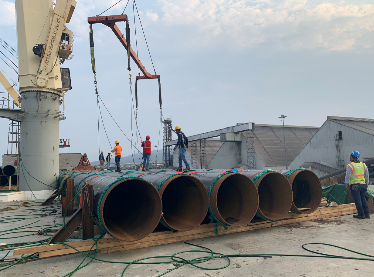
The use of pipe piles in foundation construction has been a popular choice for many years. Pipe piles are used to transfer the load of a structure to a deeper, more stable layer of soil or rock.
Benefits of Pipe Trusses The use of pipe trusses in construction offers several notable advantages: Strength and Load-bearing Capacity: Pipe trusses are renowned for their high strength-to-weight ratio. The interconnected pipes distribute loads evenly, resulting in a sturdy and reliable structure. This allows for the construction of large spans without the need for excessive support columns or beams.
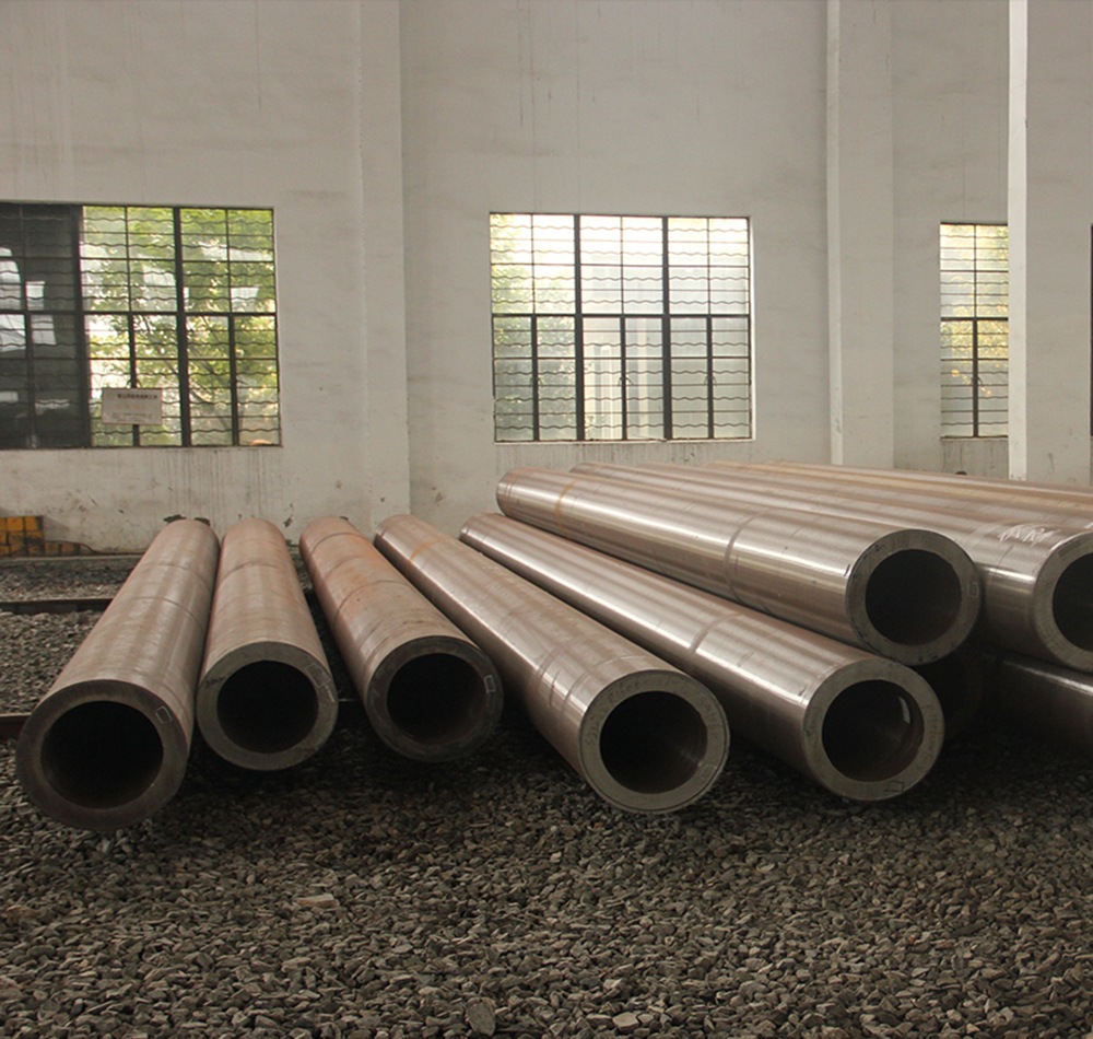
The standard for fluid-conveying seamless pipes depends on the country or region you are in, as well as the specific application. However, some widely used international standards for fluid-conveying seamless pipes are: ASTM A106: This is a standard specification for seamless carbon steel pipes for high-temperature service in the United States. It is commonly used in power plants, refineries, and other industrial applications where high temperatures and pressures are present. It covers pipes in grades A, B, and C, with varying mechanical properties depending on the grade. API 5L: This is a standard specification for line pipes used in the oil and gas industry. It covers seamless and welded steel pipes for pipeline transportation systems, including pipes for conveying gas, water, and oil. API 5L pipes are available in various grades, such as X42, X52, X60, and X65, depending on the material properties and application requirements. ASTM A53: This is a standard specification for seamless and welded black and hot-dipped galvanized steel pipes used in various industries, including fluid-conveying applications. It covers pipes in two grades, A and B, with different mechanical properties and intended uses. DIN 2448 / EN 10216: These are European standards for seamless steel pipes used in fluid-conveying applications, including water, gas, and other fluids. Read more
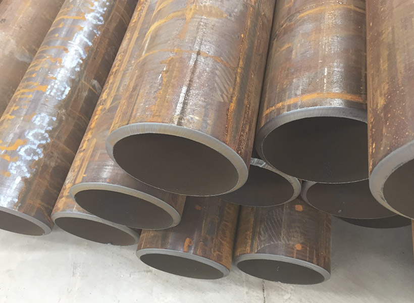
Fluid-conveying seamless pipes are designed to resist various types of corrosion depending on the material used and the specific application. Some of the most common types of corrosion that these pipes are designed to resist include: Uniform corrosion: This is the most common type of corrosion, where the entire surface of the pipe corrodes uniformly. To resist this type of corrosion, pipes are often made of corrosion-resistant materials, such as stainless steel or lined with protective coatings. Galvanic corrosion: This occurs when two dissimilar metals are in contact with each other in the presence of an electrolyte, leading to the corrosion of the more active metal. To prevent galvanic corrosion, pipes can be made of similar metals, or they can be isolated from each other using insulating materials or coatings. Pitting corrosion: Pitting is a localized form of corrosion that occurs when small areas on the pipe's surface become more susceptible to attack, leading to the formation of small pits. This type of corrosion can be prevented by using materials with high pitting resistance, such as stainless steel alloys with added molybdenum, or by applying protective coatings. Crevice corrosion: Crevice corrosion occurs in narrow spaces or gaps between two surfaces, such Read more

Wedge wire screens, also known as profile wire screens, are commonly used in various industries for their superior screening capabilities. They are constructed from triangular-shaped wire,
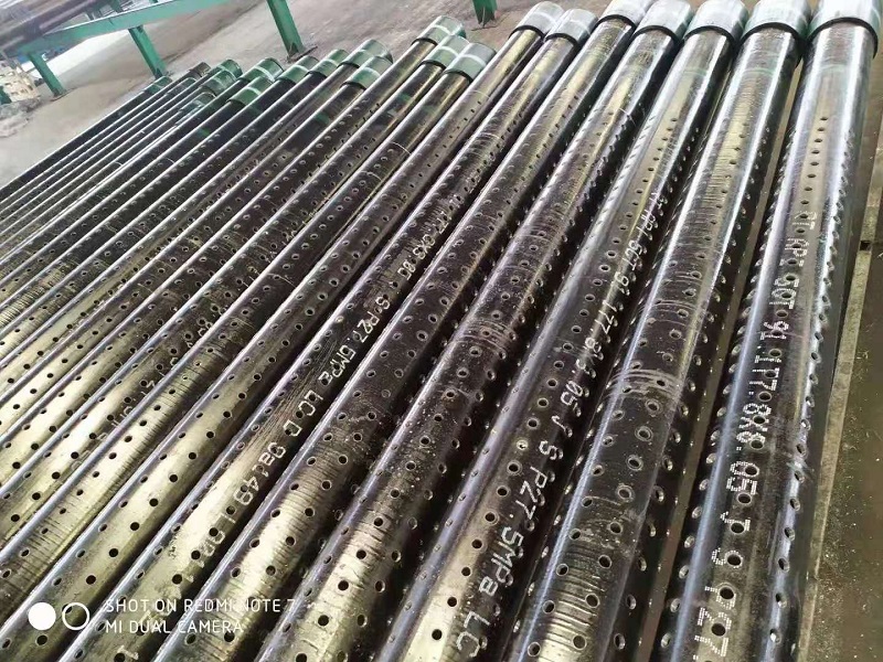
2 7/8in J55 K55 Perforated Well Casing Pipe is one of mainly products of we abter steel, they can be used for water, oil, gas well drilling fields. The thicknesss can be supplied from 5.51-11.18mm based on client's well depth and required mechanical properties. Normally they are provided with thread connection, like NUE or EUE, which will be easier to installed at site. The length of 3-12m perforated casing pipes are available for client's different drilling rigs height. The hole diameter and open area on the surface are also customized. The popular hole diameters are 9mm, 12mm, 15mm, 16mm, 19mm, etc.
