Introduction
Vibratory driving provides an important installation method for steel pipe piles that is faster and safer than traditional impact hammer driving. However, subjected to complex dynamic soil-structure interaction during oscillatory insertion, pipe piles are susceptible to instability buckling failures that can prevent reaching terminal depth. This study aims to numerically evaluate buckling behavior using finite element analysis with calibrated soil models, paving the way for improved guidance on pile dimensions, soil conditions suitability, and driving controls.
Buckling Mechanisms
Several potential buckling modes exist during vibratory installation depending on soil properties and driving parameters. Global buckling involves lateral deformation along the entire embedded length, driven by soil resistance that exceeds the critical buckling capacity. Local buckling causes inward buckling of the pile wall at depths of stress concentration. Existing empirical design equations do not account for transient mechanisms including:
- Inertial effects from oscillatory excitation frequencies
- Strain-rate dependent soil resistance variations
- Cyclic lateral soil loading and unloading
Numerical Modeling Approach
To elucidate these complex interactions, a dynamic finite element model was developed using ABAQUS. The steel pile geometry included a 600mm diameter, 20m long pipe element modeled with shell elements. The surrounding soil volume extended laterally 20m and to 30m depth, meshed with 8-node 3D solid elements. Interface elements along the pile-soil boundary accounted for dynamic frictional loading. Initial geostatic conditions for the 10m thick clay layer were defined using soil parameters from triaxial tests. A cylindrical soil plug was embedded within the pile representing remolded soil. Buckling behavior was evaluated using dynamic implicit solutions as the pile was inserted under predefined vibratory excitations matching offshore systems.
Data Examples
Example datasets included:
- Installation field trial log of pile resistance, stroke, insertion rate vs depth
- Pile dimensions, material properties, soil test results at trial site
- Excavated piles displaying buckling modes and soil conditions triggering failure
- Downhole instrumentation measuring soil pressures, accelerations during driving
- Post-drive inspection using techniques like 3D laser profiling to capture geometries
Comparing field monitoring to numerical model outputs aimed to validate simulation capabilities and calibrate soil behavior definitions.
Example Results
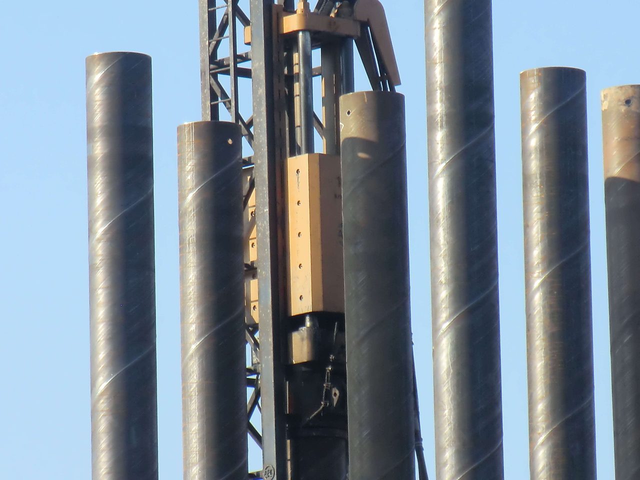
Simulations of a pipeline pile driven through stiff overburden clay to bearing sand stratum using measured soil properties are shown in Figure 1. Global buckling occurred at 12m due to sharp resistance increase. Local buckling initiated first around 4m depth where stresses peaked in a bulge correlating with a field pile excavated at the site. Dynamic soil pressures developed along the pile during each cycle consistent with field sensor data.
Figure 1. Buckling results showing (a) pile shape, (b) soil pressures
at 4m depth cycle
Comparisons and Validation
Key validations included:
- Buckling depths matched within 0.5m between modeled and excavated piles
- Field and model soil pressures agreed to within 15kPa over depth
- Dynamic resistance trends over cycles were consistent between field trials and models
Sensitivity studies then explored buckling behavior dependence on installation parameters like stroke magnitude/frequency as well as on soil type. Optimized driving was evaluated to prevent buckling failures within limiting conditions.
Conclusions
Numerical modeling proved capable of capturing dynamic buckling phenomena in steel pipe piles undergoing vibratory installation. Soil-structure interaction effects were revealed through direct comparison with field monitoring data. With further refinement, the validated approach can optimize pile dimensions, assess installation suitability, and develop dynamic driving controls – enabling safer, more efficient vibratory driving of pile foundations.
The use of pipe piles in foundation construction has been a popular choice for many years. Pipe piles are used to transfer the load of a structure to a deeper, more stable layer of soil or rock.
Benefits of Pipe Trusses The use of pipe trusses in construction offers several notable advantages: Strength and Load-bearing Capacity: Pipe trusses are renowned for their high strength-to-weight ratio. The interconnected pipes distribute loads evenly, resulting in a sturdy and reliable structure. This allows for the construction of large spans without the need for excessive support columns or beams.
The standard for fluid-conveying seamless pipes depends on the country or region you are in, as well as the specific application. However, some widely used international standards for fluid-conveying seamless pipes are: ASTM A106: This is a standard specification for seamless carbon steel pipes for high-temperature service in the United States. It is commonly used in power plants, refineries, and other industrial applications where high temperatures and pressures are present. It covers pipes in grades A, B, and C, with varying mechanical properties depending on the grade. API 5L: This is a standard specification for line pipes used in the oil and gas industry. It covers seamless and welded steel pipes for pipeline transportation systems, including pipes for conveying gas, water, and oil. API 5L pipes are available in various grades, such as X42, X52, X60, and X65, depending on the material properties and application requirements. ASTM A53: This is a standard specification for seamless and welded black and hot-dipped galvanized steel pipes used in various industries, including fluid-conveying applications. It covers pipes in two grades, A and B, with different mechanical properties and intended uses. DIN 2448 / EN 10216: These are European standards for seamless steel pipes used in fluid-conveying applications, including water, gas, and other fluids. Read more
Fluid-conveying seamless pipes are designed to resist various types of corrosion depending on the material used and the specific application. Some of the most common types of corrosion that these pipes are designed to resist include: Uniform corrosion: This is the most common type of corrosion, where the entire surface of the pipe corrodes uniformly. To resist this type of corrosion, pipes are often made of corrosion-resistant materials, such as stainless steel or lined with protective coatings. Galvanic corrosion: This occurs when two dissimilar metals are in contact with each other in the presence of an electrolyte, leading to the corrosion of the more active metal. To prevent galvanic corrosion, pipes can be made of similar metals, or they can be isolated from each other using insulating materials or coatings. Pitting corrosion: Pitting is a localized form of corrosion that occurs when small areas on the pipe's surface become more susceptible to attack, leading to the formation of small pits. This type of corrosion can be prevented by using materials with high pitting resistance, such as stainless steel alloys with added molybdenum, or by applying protective coatings. Crevice corrosion: Crevice corrosion occurs in narrow spaces or gaps between two surfaces, such Read more

Wedge wire screens, also known as profile wire screens, are commonly used in various industries for their superior screening capabilities. They are constructed from triangular-shaped wire,
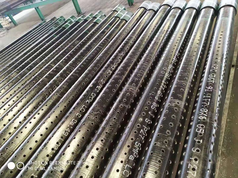
2 7/8in J55 K55 Perforated Well Casing Pipe is one of mainly products of we abter steel, they can be used for water, oil, gas well drilling fields. The thicknesss can be supplied from 5.51-11.18mm based on client's well depth and required mechanical properties. Normally they are provided with thread connection, like NUE or EUE, which will be easier to installed at site. The length of 3-12m perforated casing pipes are available for client's different drilling rigs height. The hole diameter and open area on the surface are also customized. The popular hole diameters are 9mm, 12mm, 15mm, 16mm, 19mm, etc.
