Analyzing the fatigue response of steel pipe piles under adverse sea conditions is essential for ensuring the structural integrity and longevity of offshore structures such as oil platforms, wind turbines, and piers. These piles are subjected to dynamic loading from waves, currents, and wind, which can lead to fatigue damage over time. This comprehensive analysis explores the factors affecting fatigue response, methodologies for fatigue analysis, and strategies for mitigating fatigue damage in steel pipe pile.
Introduction to Fatigue in Steel Pipe Pile
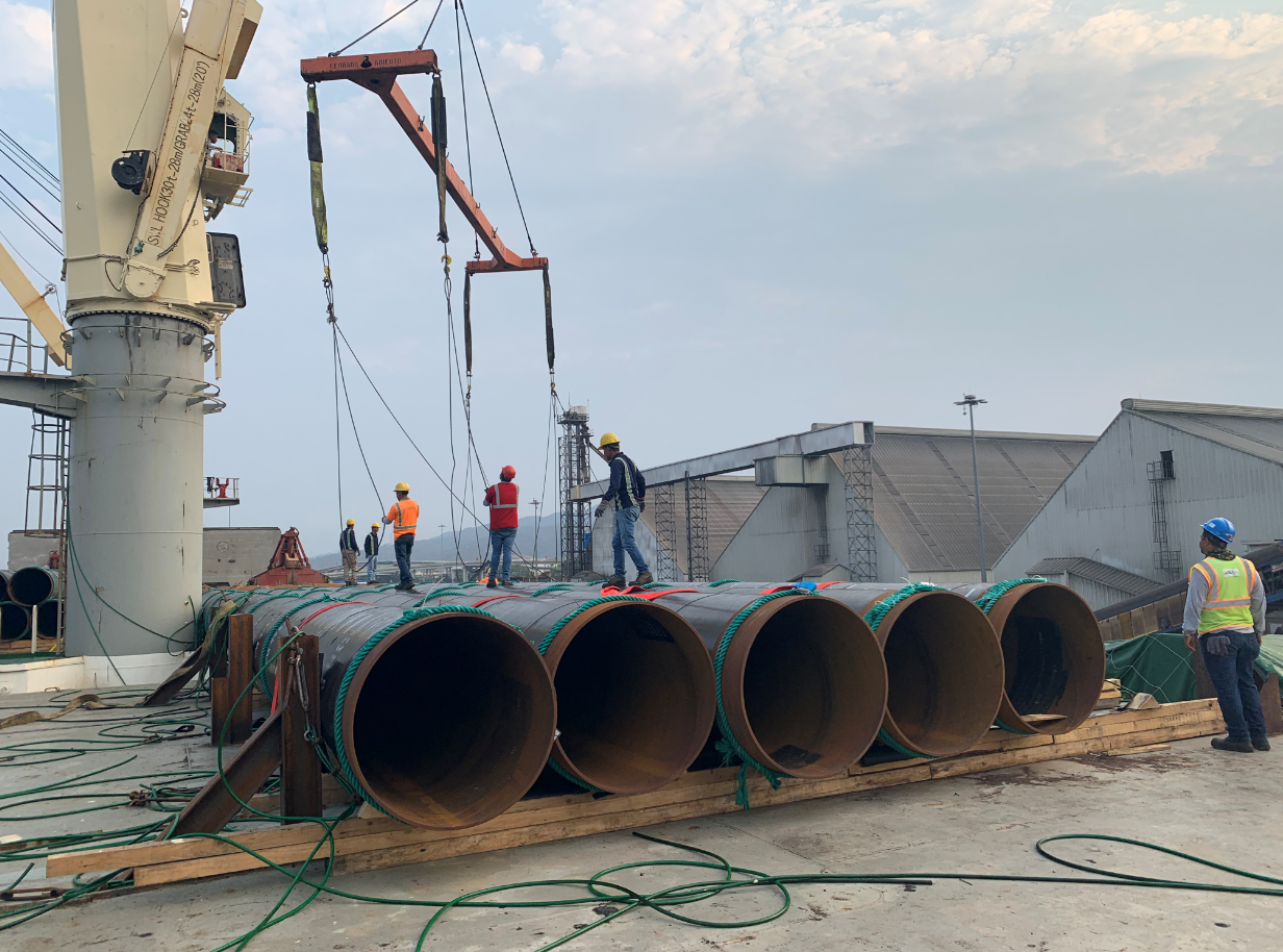
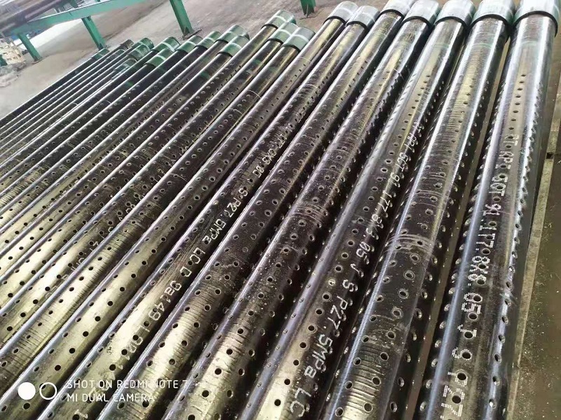
Steel Pipe Pile are a critical component of offshore structures, providing foundational support in challenging marine environments. Fatigue refers to the progressive and localized structural damage that occurs when a material is subjected to cyclic loading. In the context of Steel Pipe Pile, fatigue can lead to crack initiation and propagation, ultimately resulting in failure if not properly managed.
Factors Influencing Fatigue Response
- Material Properties
- Steel Grade: The mechanical properties of the steel, such as yield strength, tensile strength, and toughness, influence its fatigue resistance.
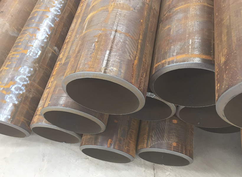
- Weld Quality: Welds are common sites for fatigue crack initiation due to stress concentrations and potential defects.
- Environmental Conditions
- Wave and Current Loading: Cyclic loading from waves and currents induces fluctuating stresses in the piles, contributing to fatigue damage.
- Corrosive Environment: Exposure to seawater and marine organisms can accelerate corrosion, reducing the fatigue life of the piles.
- Geometric and Structural Factors
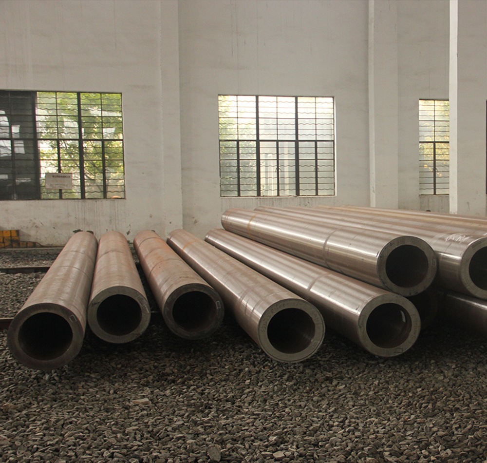
- Pile Diameter and Wall Thickness: Larger diameters and thicker walls generally enhance fatigue resistance by reducing stress concentrations.
- Pile Configuration: The arrangement and orientation of piles in a structure can affect the distribution of loads and stress concentrations.
- Operational Conditions
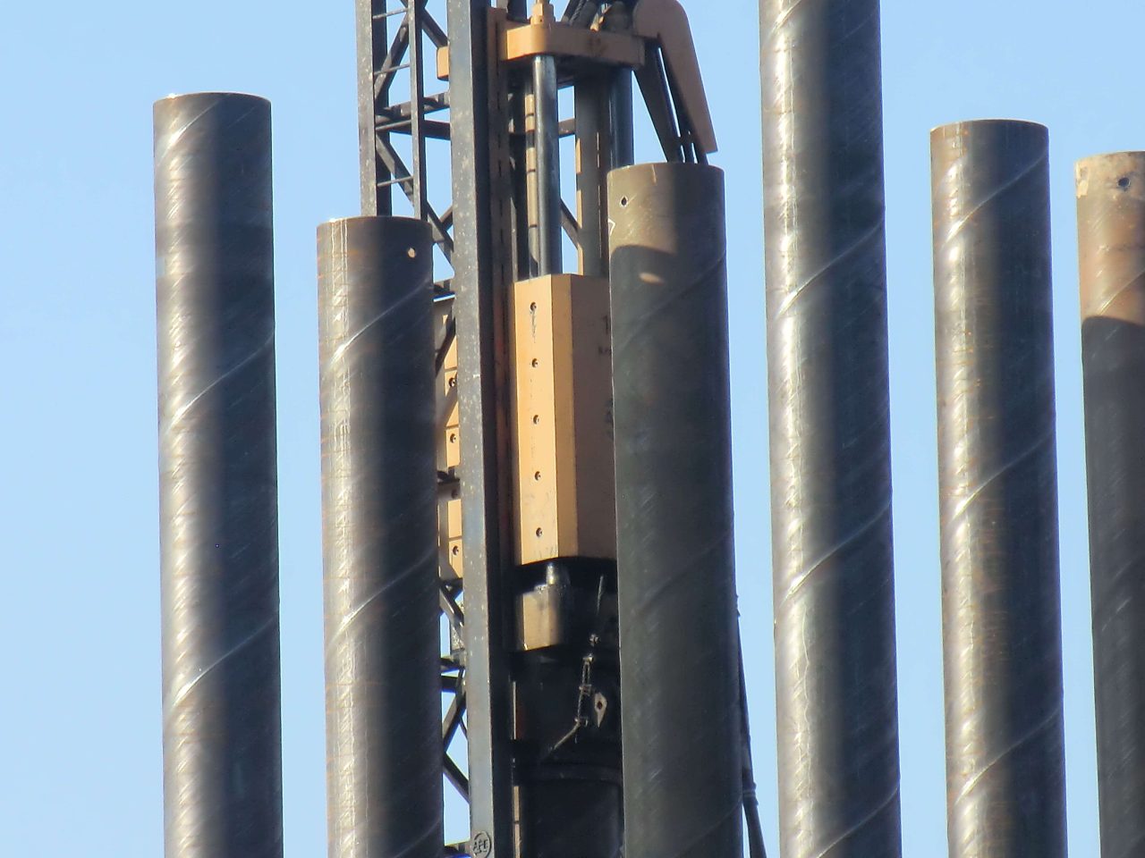
- Installation Method: The method of installation, such as driving or drilling, can introduce residual stresses that affect fatigue response.
- Service Life and Load History: The cumulative effect of load cycles over the service life of the pile influences its fatigue performance.
Methodologies for Fatigue Analysis
- S-N Curve Approach
- Principle: The S-N curve (stress-life curve) represents the relationship between stress amplitude and the number of cycles to failure. It is derived from experimental data and used to estimate fatigue life.
- Application: Suitable for high-cycle fatigue analysis where the stress levels are below the material’s yield strength.
- Fracture Mechanics Approach
- Principle: This approach focuses on the growth of existing cracks, using parameters such as stress intensity factor and crack growth rate to predict fatigue life.
- Application: Ideal for low-cycle fatigue analysis and situations where pre-existing cracks or defects are present.
- Finite Element Analysis (FEA)
- Principle: FEA involves creating a computational model of the pile and simulating the effects of cyclic loading to assess stress distribution and identify critical areas.
- Application: Provides detailed insights into complex geometries and loading conditions, allowing for more accurate fatigue predictions.
- Probabilistic Fatigue Analysis
- Principle: This method incorporates variability in material properties, loading conditions, and environmental factors to assess the probability of fatigue failure.
- Application: Useful for risk assessment and decision-making in the design and maintenance of offshore structures.
Fatigue Response Analysis: Case Study
Scenario Description
In this case study, we analyze the fatigue response of a steel pipe pile foundation for an offshore wind turbine. The piles are subjected to cyclic loading from waves and wind, with additional considerations for corrosive seawater exposure.
Material Properties and Geometric Parameters
| Parameter | Value |
|---|---|
| Steel Grade | ASTM A252 Grade 3 |
| Yield Strength | 310 MPa |
| Tensile Strength | 455 MPa |
| Pile Diameter | 1.5 meters |
| Wall Thickness | 25 mm |
| Weld Quality | High (AWS D1.1) |
Environmental and Loading Conditions
| Condition | Description |
|---|---|
| Wave Height | 3 meters (average) |
| Wave Period | 8 seconds |
| Current Speed | 1.5 m/s |
| Wind Speed | 20 m/s |
| Corrosion Rate | 0.1 mm/year |
Fatigue Analysis Approach
- S-N Curve Analysis
- Data Source: S-N curves for ASTM A252 Grade 3 steel are obtained from experimental fatigue tests.
- Stress Range Calculation: The stress range is calculated based on wave and current loading, considering the pile’s geometric and material properties.
- Fatigue Life Estimation: Using the S-N curve, the number of cycles to failure is estimated for the calculated stress range.
- Fracture Mechanics Analysis
- Initial Crack Size: Assumed initial crack size of 2 mm, based on weld inspection data.
- Crack Growth Rate: Paris’ law is used to model crack growth, with parameters obtained from literature for similar steel grades.
- Fatigue Life Prediction: The remaining fatigue life is predicted by integrating the crack growth rate over the expected service life.
- Finite Element Analysis (FEA)
- Model Setup: A 3D FEA model of the pile is created, incorporating geometric details and material properties.
- Loading Simulation: Cyclic loading from waves and wind is applied, and the stress distribution is analyzed.
- Critical Areas Identification: Areas with high stress concentrations are identified as potential sites for fatigue crack initiation.
- Probabilistic Fatigue Analysis
- Input Variability: Variability in material properties, loading conditions, and environmental factors is incorporated into the analysis.
- Failure Probability Assessment: The probability of fatigue failure is assessed over the expected service life, providing insights into risk levels.
Results and Discussion
S-N Curve Analysis Results
| Stress Range (MPa) | Cycles to Failure |
|---|---|
| 150 | 1,000,000 |
| 200 | 500,000 |
| 250 | 200,000 |
- Observation: The estimated fatigue life decreases with increasing stress range. For the average stress range of 200 MPa, the fatigue life is approximately 500,000 cycles.
Fracture Mechanics Analysis Results
| Crack Size (mm) | Remaining Life (cycles) |
|---|---|
| 2 | 300,000 |
| 5 | 150,000 |
| 10 | 50,000 |
- Observation: The presence of an initial crack significantly reduces the remaining fatigue life. Regular inspections and crack monitoring are essential for managing fatigue risk.
FEA Results
- Stress Concentration Areas: The FEA model identified high stress concentrations at the weld joints and pile-soil interface, indicating potential sites for fatigue crack initiation.
- Design Recommendations: Reinforcement of critical areas and improved weld quality can enhance fatigue resistance.
Probabilistic Fatigue Analysis Results
| Probability of Failure (%) | Service Life (years) |
|---|---|
| 5 | 20 |
| 10 | 15 |
| 20 | 10 |
- Observation: The probability of failure increases with service life. Implementing protective measures and regular maintenance can reduce the risk of fatigue failure.
Strategies for Mitigating Fatigue Damage
- Material Selection and Design
- High-Strength Steel: Using high-strength steel with superior fatigue resistance can extend the service life of piles.
- Optimized Design: Designing piles with reduced stress concentrations and improved load distribution enhances fatigue performance.
- Weld Quality Improvement
- Weld Inspection and Repair: Regular inspection and repair of welds can prevent crack initiation and propagation.
- Advanced Welding Techniques: Employing advanced welding techniques, such as friction stir welding, can improve weld quality and reduce defects.
- Corrosion Protection
- Coatings and Cathodic Protection: Applying protective coatings and implementing cathodic protection systems can mitigate corrosion and extend fatigue life.
- Regular Maintenance: Routine maintenance, including cleaning and recoating, helps preserve the integrity of protective measures.
- Monitoring and Inspection
- Structural Health Monitoring: Implementing structural health monitoring systems with sensors can provide real-time data on pile condition and detect early signs of fatigue damage.
- Regular Inspections: Conducting regular inspections using non-destructive testing methods, such as ultrasonic testing, helps identify and address fatigue issues before they lead to failure.
Conclusion
The fatigue response analysis of Steel Pipe Pile under adverse sea conditions highlights the importance of understanding the factors influencing fatigue performance and employing appropriate analysis methodologies. By considering material properties, environmental conditions, and operational factors, engineers can design and maintain offshore structures to withstand the challenges of marine environments. Implementing strategies for mitigating fatigue damage, such as material selection, design optimization, and regular monitoring, ensures the long-term reliability and safety of Steel Pipe Pile in offshore applications. As technology advances, the ability to accurately predict and manage fatigue response will continue to improve, contributing to more resilient and sustainable offshore infrastructure.