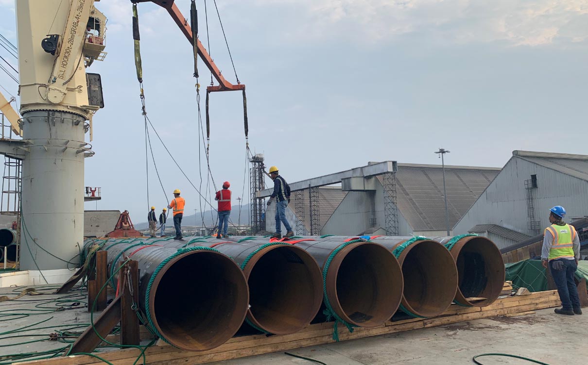
WELDED Steel Pipe Piles (ERW ,LASW, DSAW ,SSAW.)
The two most common methods for steel pipe welding are straight seam or spiral seam welding. Welded steel pipes are typically used to transport fluid (water or oil) and natural gas. It is typically less expensive than seamless steel pipe. Both types of welding are applied after the pipe has been rolled, which involves shaping a sheet of steel into the end shape.
Straight Seam: Straight seam welded steel pipes are manufactured by adding a welding parallel to the pipe seam. The process is fairly straightforward: Straight seam pipes are formed when a sheet of steel is bent and formed into a pipe shape, then welded longitudinally. Straight seam pipes can be submerged arc welded (SAW) or double-submerged arc welded (DSAW).
Spiral Seam: Spiral seam welded pipes are manufactured when hot-rolled strip steel is formed into a pipe through spiral bending and welded along the then spiraled seam of the pipe. This results in the weld length being 30-100% longer than that of a straight seam welded pipe. This method is more commonly used on large diameter pipe. (Note: this method of welding may also be referred to as helical submerged arc welded, or HSAW. Spiral seam pipes are also available as DSAW.)
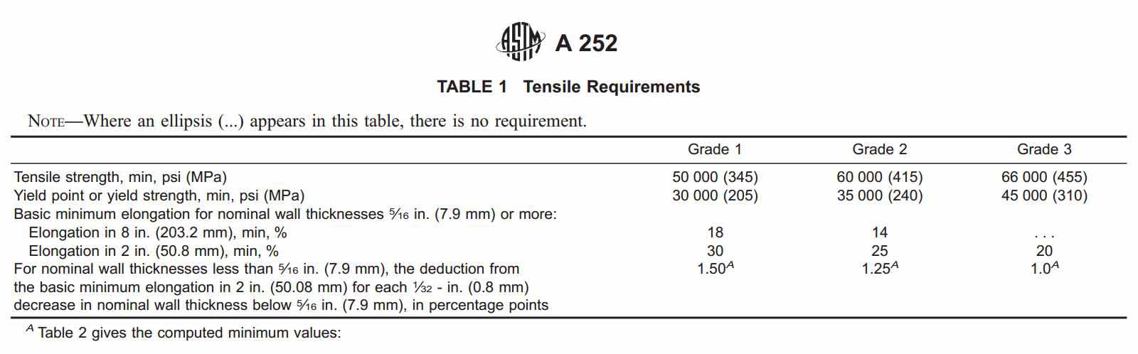
There are three grades under the A252 Pipe Pile Specification, and they are as follows:
Specifications
As per the specification, the weight of the pipe cannot vary by 15% over or 5% under the theoretical weight. Moreover, the outside diameter cannot vary more than + or – 1% of the OD or 12.5% under the nominal wall thickness.
The length ranges under this spec are as follows:
- Single Random Lengths: 16 to 25 ft
- Double Random Lengths: Over 25 ft with min, average of 35 feet
A252 pipe can either have plain ends, done by either flame-cuts or machine-end cuts. When bevels are required, they are to be beveled at an angle of 30 +5 degrees.
For more information, please review the ASTM guidelines.
A252 Pipe Pile Popular Grade Sizes Tube & Metal
We have sizes available up to 120”. Contact us for details.
Chemical composition and mechanical properties of ASTM A252 Pipe Pile
The standard has a limit for element P (phosphorous) maximum 0.050%, since P will make steel fragile, and most important is not good for welding performances. ASTM A252 standard specifications only defines the conten of phosphorous, other elements accord with general carbon steel material.
Mechanical Properties of A252 Pipe Pile
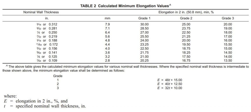
Enlongations
ASTM A252/A252M-19 Standard Specification for Welded and Seamless Steel Pipe Piles
Abstract
This specification covers nominal wall cylindrical steel pipe piles in which the steel cylinder acts as a permanent load-carrying member or as a shell to form cast-in-place concrete piles. Each welded pile shall be made by seamless, electric resistance welding, flash welding or fusion welding with longitudinal, helical-butt, or helical-lap seams. This specification also deals with material tensile requirements, minimum elongation values and common size and weights per unit length values.
Scope
1.1 This specification covers nominal (average) wall steel pipe piles of cylindrical shape and applies to pipe piles in which the steel cylinder acts as a permanent load-carrying member, or as a shell to form cast-in-place concrete piles. Pipe piles are produced as both welded and seamless products.
1.2 This specification is expressed in both inch-pound units and SI units; however, unless the purchase order or contract specifies the applicable M specification designation (SI units), the inch-pound units shall apply. The values stated in either inch-pound or SI units are to be regarded separately as standard. Within the text, the SI units are shown in brackets. The values stated in each system may not be exact equivalents; therefore, each system shall be used independently of the other. Combining values from two systems may result in nonconformance with the standard.
1.3 The text of this specification contains notes and footnotes that provide explanatory material. Such notes and footnotes, excluding those in tables and figures, do not contain any mandatory requirements.
1.4 The following precautionary caveat pertains only to the test method portion, Section 16 of this specification. This standard does not purport to address all of the safety problems, if any, associated with its use. It is the responsibility of the user of this standard to establish appropriate safety, health, and environmental practices and determine the applicability of regulatory limitations prior to use.
1.5 This international standard was developed in accordance with internationally recognized principles on standardization established in the Decision on Principles for the Development of International Standards, Guides and Recommendations issued by the World Trade Organization Technical Barriers to Trade (TBT) Committee.