Carbon Steel Sheet Pile Design Analysis
Carbon steel sheet piles are widely used in civil engineering for retaining structures, cofferdams, and foundation systems. This design analysis explores the structural behavior of carbon steel sheet piles, focusing on their material properties, loading conditions, and design methodologies. It includes parameter tables, formulas, and practical considerations to guide engineers in optimizing sheet pile designs.
1. Material Properties of Carbon Steel Sheet Piles
Carbon steel sheet piles are typically manufactured from low-to-medium carbon steel grades (e.g., S235, S275, S355 per EN standards), offering a balance of strength, ductility, and cost. The material properties influence the pile’s ability to resist bending, shear, and local buckling.
| Property | Value | Unit |
|---|---|---|
| Yield Strength (σ_y) | 235–500 | MPa |
| Ultimate Tensile Strength (σ_u) | 360–600 | MPa |
| Modulus of Elasticity (E) | 210 | GPa |
| Poisson’s Ratio (ν) | 0.3 | – |
| Density (ρ) | 7850 | kg/m³ |
2. Design Parameters
Key design parameters for carbon steel sheet piles include section modulus, moment of inertia, and interlock strength, which determine their capacity to resist lateral loads and maintain stability.
| Parameter | Symbol | Typical Range | Unit |
|---|---|---|---|
| Section Modulus | W | 500–5000 | cm³/m |
| Moment of Inertia | I | 10,000–200,000 | cm⁴/m |
| Wall Thickness | t | 2–25 | mm |
| Width | b | 400–900 | mm |
| Height | h | 200–600 | mm |
3. Loading Conditions
Sheet piles are subjected to lateral earth pressure, hydrostatic pressure, and surcharge loads. The active earth pressure (P_a) is calculated using Rankine’s theory:
P_a = 0.5 × K_a × γ × H²
Where:
- P_a = Active earth pressure (kN/m²)
- K_a = Active earth pressure coefficient = (1 – sinφ) / (1 + sinφ)
- γ = Soil unit weight (kN/m³)
- H = Wall height (m)
- φ = Angle of internal friction (degrees)
For a typical sandy soil (φ = 30°, γ = 18 kN/m³, H = 5 m), P_a = 75 kN/m².
4. Structural Analysis
4.1 Bending Moment Capacity
The maximum bending moment (M) a sheet pile can resist is:
M = σ_y × W / γ_m
Where:
- M = Moment capacity (kNm/m)
- σ_y = Yield strength (MPa)
- W = Section modulus (cm³/m)
- γ_m = Material safety factor (typically 1.15)
For an S355 pile (σ_y = 355 MPa, W = 1800 cm³/m), M = 555 kNm/m.
4.2 Deflection
Deflection (δ) under lateral load is calculated using beam theory:
δ = (w × L⁴) / (8 × E × I)
Where:
- δ = Maximum deflection (mm)
- w = Uniform lateral load (kN/m)
- L = Embedded length (m)
- E = Modulus of elasticity (210 GPa)
- I = Moment of inertia (cm⁴/m)
For w = 20 kN/m, L = 6 m, I = 50,000 cm⁴/m, δ ≈ 3.4 mm.
4.3 Local Buckling
Thin-walled sections risk local buckling. The critical buckling stress (σ_cr) is:
σ_cr = k × (π² × E) / [12 × (1 - ν²) × (b/t)²]
Where:
- k = Buckling coefficient (e.g., 4 for simply supported edges)
- b/t = Width-to-thickness ratio
For b/t = 50, σ_cr ≈ 336 MPa, which must exceed applied stress.
4.4 Interlock Strength
Interlock shear capacity (F_s) ensures wall integrity:
F_s = τ × A_interlock
Where:
- τ = Shear strength (≈ 0.6 × σ_y)
- A_interlock = Interlock area (mm²)
For σ_y = 355 MPa, A_interlock = 200 mm², F_s ≈ 42.6 kN/m.
5. Design Considerations
Key considerations include:
- Embedment Depth: Determined by equilibrium of moments and forces, typically 1.5–2 times the exposed height.
- Corrosion: Carbon steel corrodes in marine environments; protective coatings or allowances (e.g., 1–2 mm) are required.
- Driving Conditions: Hard soils may require thicker sections or higher yield strength.
6. Example Design
For a 5 m retaining wall in sandy soil (φ = 30°, γ = 18 kN/m³):
- P_a = 75 kN/m²
- Required W = (P_a × H² / 8) × γ_m / σ_y = 1800 cm³/m (S355 steel)
- Embedment depth ≈ 7.5 m (1.5H)
Select an AZ 18-700 pile (W = 1800 cm³/m, σ_y = 355 MPa).
Carbon steel sheet pile design involves balancing material strength, section properties, and environmental loads. By applying the formulas and parameters above, engineers can ensure stability, safety, and efficiency in applications ranging from temporary cofferdams to permanent retaining structures.
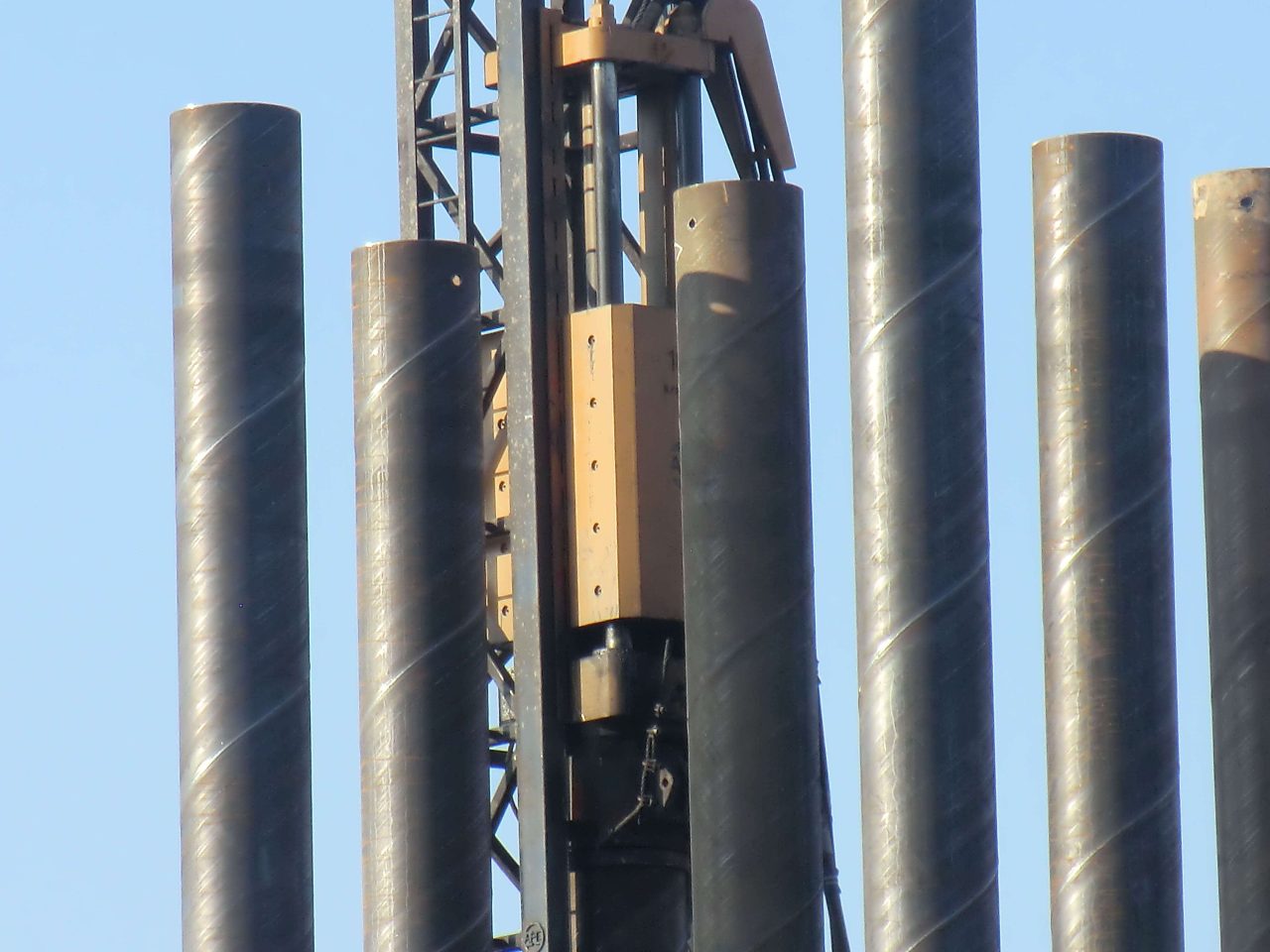
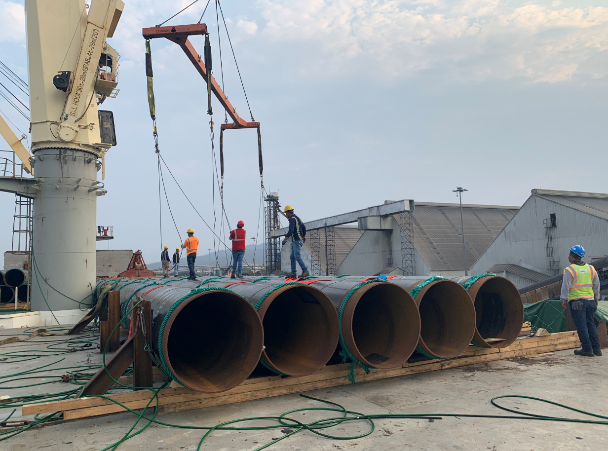
The use of pipe piles in foundation construction has been a popular choice for many years. Pipe piles are used to transfer the load of a structure to a deeper, more stable layer of soil or rock.
Benefits of Pipe Trusses The use of pipe trusses in construction offers several notable advantages: Strength and Load-bearing Capacity: Pipe trusses are renowned for their high strength-to-weight ratio. The interconnected pipes distribute loads evenly, resulting in a sturdy and reliable structure. This allows for the construction of large spans without the need for excessive support columns or beams.
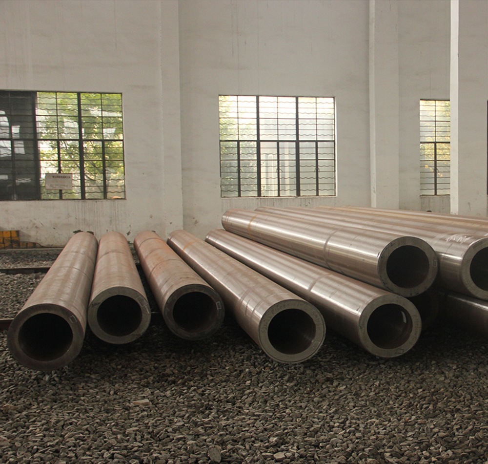
The standard for fluid-conveying seamless pipes depends on the country or region you are in, as well as the specific application. However, some widely used international standards for fluid-conveying seamless pipes are: ASTM A106: This is a standard specification for seamless carbon steel pipes for high-temperature service in the United States. It is commonly used in power plants, refineries, and other industrial applications where high temperatures and pressures are present. It covers pipes in grades A, B, and C, with varying mechanical properties depending on the grade. API 5L: This is a standard specification for line pipes used in the oil and gas industry. It covers seamless and welded steel pipes for pipeline transportation systems, including pipes for conveying gas, water, and oil. API 5L pipes are available in various grades, such as X42, X52, X60, and X65, depending on the material properties and application requirements. ASTM A53: This is a standard specification for seamless and welded black and hot-dipped galvanized steel pipes used in various industries, including fluid-conveying applications. It covers pipes in two grades, A and B, with different mechanical properties and intended uses. DIN 2448 / EN 10216: These are European standards for seamless steel pipes used in fluid-conveying applications, including water, gas, and other fluids. Read more
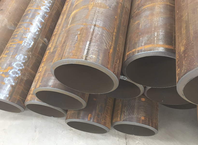
Fluid-conveying seamless pipes are designed to resist various types of corrosion depending on the material used and the specific application. Some of the most common types of corrosion that these pipes are designed to resist include: Uniform corrosion: This is the most common type of corrosion, where the entire surface of the pipe corrodes uniformly. To resist this type of corrosion, pipes are often made of corrosion-resistant materials, such as stainless steel or lined with protective coatings. Galvanic corrosion: This occurs when two dissimilar metals are in contact with each other in the presence of an electrolyte, leading to the corrosion of the more active metal. To prevent galvanic corrosion, pipes can be made of similar metals, or they can be isolated from each other using insulating materials or coatings. Pitting corrosion: Pitting is a localized form of corrosion that occurs when small areas on the pipe's surface become more susceptible to attack, leading to the formation of small pits. This type of corrosion can be prevented by using materials with high pitting resistance, such as stainless steel alloys with added molybdenum, or by applying protective coatings. Crevice corrosion: Crevice corrosion occurs in narrow spaces or gaps between two surfaces, such Read more

Wedge wire screens, also known as profile wire screens, are commonly used in various industries for their superior screening capabilities. They are constructed from triangular-shaped wire,
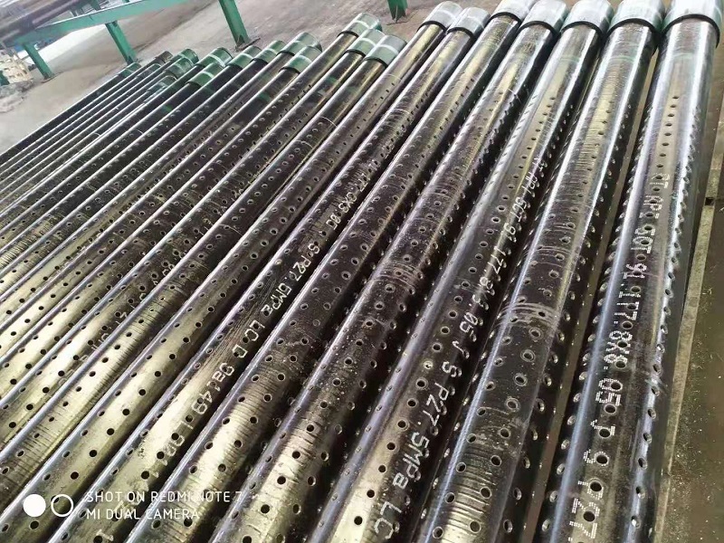
2 7/8in J55 K55 Perforated Well Casing Pipe is one of mainly products of we abter steel, they can be used for water, oil, gas well drilling fields. The thicknesss can be supplied from 5.51-11.18mm based on client's well depth and required mechanical properties. Normally they are provided with thread connection, like NUE or EUE, which will be easier to installed at site. The length of 3-12m perforated casing pipes are available for client's different drilling rigs height. The hole diameter and open area on the surface are also customized. The popular hole diameters are 9mm, 12mm, 15mm, 16mm, 19mm, etc.
