Introduction
The use of pipe piles in foundation construction has been a popular choice for many years. Pipe piles are used to transfer the load of a structure to a deeper, more stable layer of soil or rock. However, in soft ground conditions, traditional pipe pile methods may not be appropriate due to the risk of pile buckling or deformation. In this paper, we will explore the various pipe pile methods available that are appropriate for soft ground conditions.
PILE CAPACITIES
2.1 Axial Capacity
Prior to discussing the actual pile load tests performed and the results and conclusions from those
tests, a brief review of pile capacity in general is provided. In general, as mentioned earlier, a
pile in soil is effective as a deep-foundation solution because it most often transfers some
axially-applied load to usually deeper soils and reduces settlement. This transfer of the load is a
phenomenon that takes place due to the interaction of the soil and pile and the soil near the base
of the pile. In other words, the ultimate axial capacity, Qu, that a pile can have is the summation
of the skin friction developed between the sides of the pile and the soil, Qs, and the bearing
capacity of the soil at the tip of the pile, Qp (Das, 2004) such that
Qu Qp Qs ……………………………………………………(Eq. 2.1)
This is shown in Figure 2.1 for a pile driven into a soil a distance, L, from the surface and
summing axial forces.
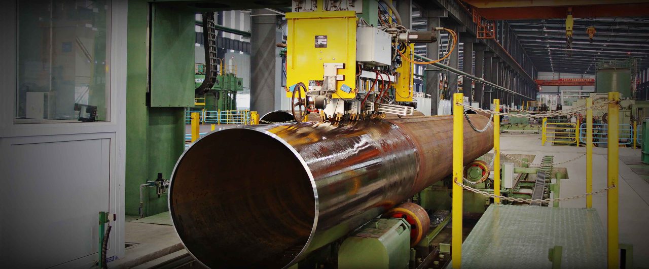
Product Description
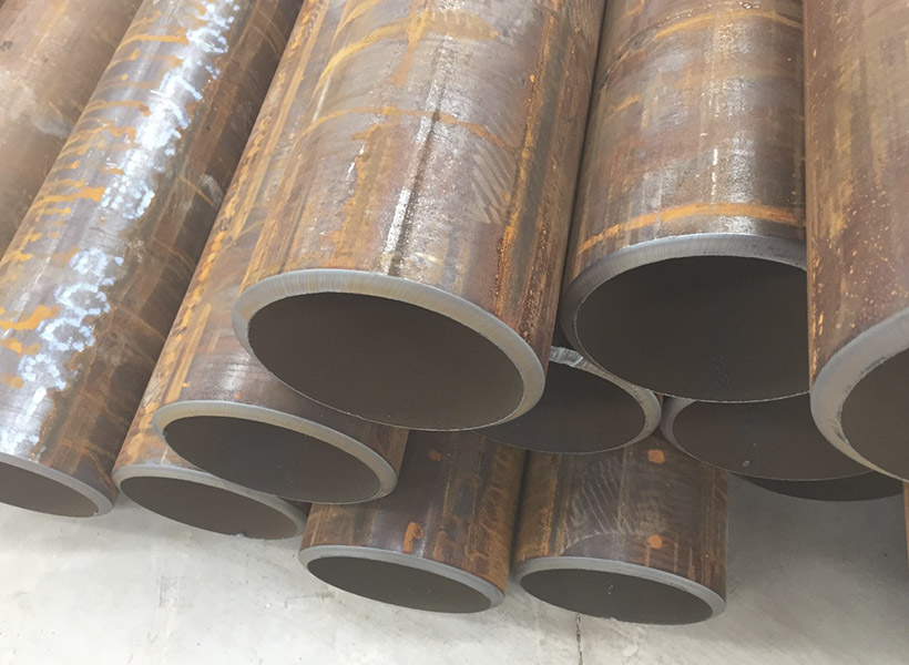
| Product Name | Welded Steel Pipe/Tube | Technique | Welded |
| Length | 5.8m-12m or as your request | Tolerance | Wall Thickness:±0.05MM Length:±6mm Outer Diameter:±0.3MM |
| Wall Thickness | 1mm-12mm or as your request | Outside Diameter | 20mm-508mm or as your request |
| Standard | API 5L ASTM A53-2007 ASTM A671-2006 ASTM A252-1998 ASTM A450-1996 ASME B36.10M-2004 ASTM A523-1996 BS 1387 BS EN10296 BS 6323 BS 6363 BS EN10219 GB/T 3091-2001 GB/T 13793-1992 GB/T9711 |
Grade | SPCC SPCD SPCE ST12-15 DC01-06 Q195A-Q235A Q195AF-Q235AF Q295A(B)-Q345A(B) |
| Pipe Ends | Beveled/Protected by plastic caps on both ends/Cut quare/Grooved/Threaded and Coupling etc. | Application | Widely used in furniture,interior decoration, fluid pipeline, petroleum and natural gas industry, drilling, pipeline, structure |
| Certificates | API/BIS/SABS/JIS/GS/ISO9001 | Delivery Time | 15-21 days |
1 Schematic showing a typical pile driven into soil and the forces
involved in determining pile capacity.
Once the pile is driven and sets up and the load that the pile must resist is increased, the loadcarrying capacities along the shaft and at the tip are mobilized. The part of the load carried by
the shaft varies along the length of the pile such that it is maximum near the ground surface and
curvilinearly decreases down to the part of the load carried by the pile tip. Lymon Reese and his
colleagues capture this generally-accepted explanation in Figure 2.2 (Reese et. al, 2006).
The unit frictional resistance along the shaft, f, on the other hand, is a ratio of the unit loadcarrying capacity along the shaft, ΔQs, to the product of the perimeter of the pile, p, and the unit
length along the shaft, ΔL, such that
p L
Q f s
……………………………..………………………..(Eq. 2.2)
This unit friction along the shaft varies such that it is zero near the ground surface, increases
curvilinearly to some maximum value near 65% of the depth of the pile from the ground surface
then curvilinearly decreases to some value greater than zero at the tip of the pile as shown in
Figure 2.3.
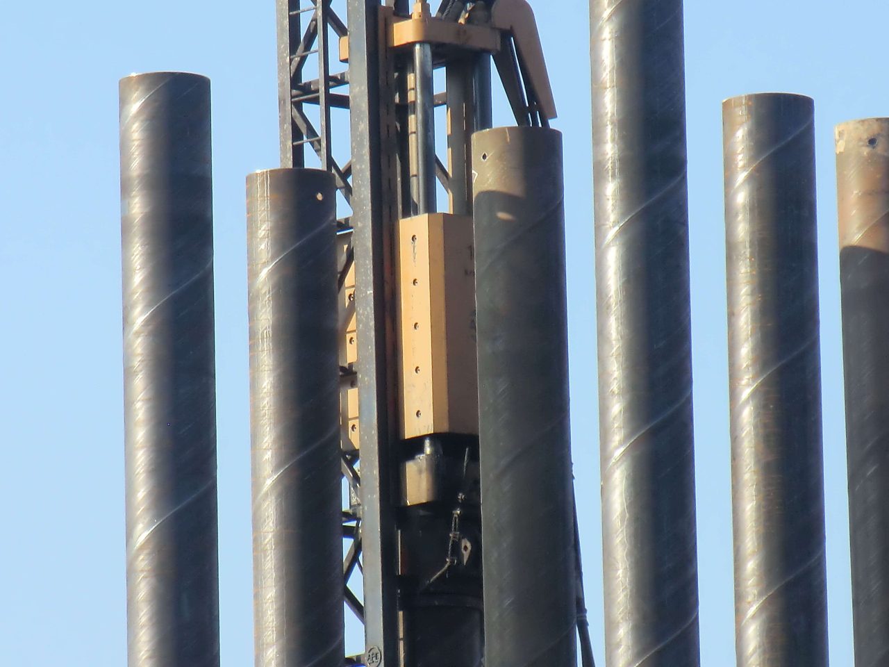
The phenomenon of the axially-applied load being transferred to the soil and hence the loadcarrying capacity of the pile is highly dependent on the method of installation (Reese et. al,
2006). Though piles can be installed via boring and vibrating, the piles that this research will
focus on were installed via the common technique of driving. Other aspects that could affect the
load-transfer process are the material the piles are being driven into and the types of piles
themselves. Next, the types of soils and the manner in which axial pile capacities are developed
in each will be explained. Afterwards, the actual piles used at each pile load test site and their
theoretical capacities will be discussed.
Background
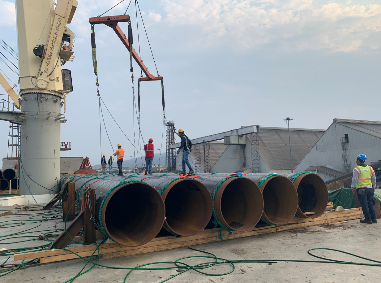
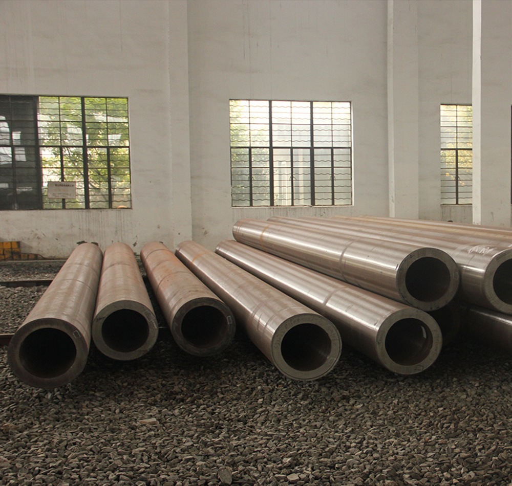
Pipe piles are typically made of steel or concrete and come in various shapes and sizes. They are commonly used in foundation construction to support structures such as buildings, bridges, and offshore platforms. Pipe piles are driven into the ground using a pile driver, which forces the pile into the soil until it reaches a predetermined depth. Once the pile is in place, it provides a strong and stable foundation for the structure being built.
In soft ground conditions, traditional pipe pile methods may not be appropriate due to the risk of pile buckling or deformation. Soft ground conditions are characterized by low soil strength, high compressibility, and high water content. These conditions can cause the pile to deform or buckle under the weight of the structure being built, which can compromise the stability of the foundation.
Pipe Pile Methods for Soft Ground
There are several pipe pile methods available that are appropriate for soft ground conditions. These methods are designed to minimize the risk of pile buckling or deformation and provide a strong and stable foundation for the structure being built.
Steel Pipe Piles with Helical Plates
Steel pipe piles with helical plates are a popular choice for soft ground conditions. These piles are made of steel and have helical plates attached to the pile shaft. The helical plates act as anchors, providing additional support and stability to the pile. The helical plates are typically installed at intervals along the pile shaft, with the distance between the plates determined by the soil conditions.
The installation process for steel pipe piles with helical plates is similar to traditional pipe piles. The pile is driven into the ground using a pile driver, and the helical plates are screwed into the soil as the pile is driven deeper. The helical plates provide additional support and stability to the pile, reducing the risk of pile buckling or deformation.
Steel Pipe Piles with Pre-Bored Holes
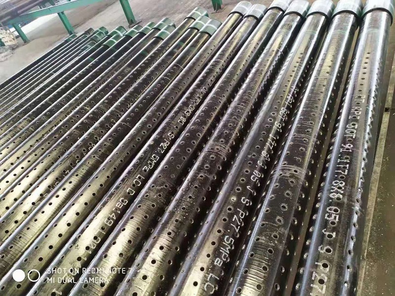
Steel pipe piles with pre-bored holes are another option for soft ground conditions. These piles are made of steel and have pre-bored holes along the pile shaft. The pre-bored holes are typically filled with grout or concrete, providing additional support and stability to the pile.
The installation process for steel pipe piles with pre-bored holes is similar to traditional pipe piles. The pile is driven into the ground using a pile driver, and the pre-bored holes are filled with grout or concrete as the pile is driven deeper. The grout or concrete provides additional support and stability to the pile, reducing the risk of pile buckling or deformation.
Steel Pipe Piles with Steel Sleeves
Steel pipe piles with steel sleeves are another option for soft ground conditions. These piles are made of steel and have steel sleeves attached to the pile shaft. The steel sleeves act as a reinforcement, providing additional support and stability to the pile.
The installation process for steel pipe piles with steel sleeves is similar to traditional pipe piles. The pile is driven into the ground using a pile driver, and the steel sleeves are attached to the pile shaft as the pile is driven deeper. The steel sleeves provide additional support and stability to the pile, reducing the risk of pile buckling or deformation.
Concrete-Filled Steel Pipe Piles
Concrete-filled steel pipe piles are another option for soft ground conditions. These piles are made of steel and are filled with concrete. The concrete provides additional support and stability to the pile, reducing the risk of pile buckling or deformation.
The installation process for concrete-filled steel pipe piles is similar to traditional pipe piles. The pile is driven into the ground using a pile driver, and the pile is filled with concrete as the pile is driven deeper. The concrete provides additional support and stability to the pile, reducing the risk of pile buckling or deformation.
Conclusion
In conclusion, there are several pipe pile methods available that are appropriate for soft ground conditions. These methods are designed to minimize the risk of pile buckling or deformation and provide a strong and stable foundation for the structure being built. Steel pipe piles with helical plates, steel pipe piles with pre-bored holes, steel pipe piles with steel sleeves, and concrete-filled steel pipe piles are all viable options for soft ground conditions. The choice of method will depend on the specific soil conditions and the requirements of the structure being built. It is important to consult with a qualified engineer to determine the most appropriate pipe pile method for a given project.

