Comprehensive Study on Construction Methods for Large-Diameter Steel Pipe Piles
1. Introduction
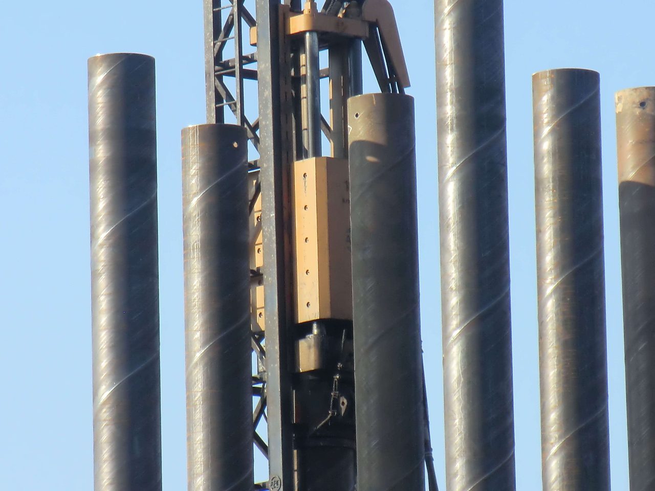
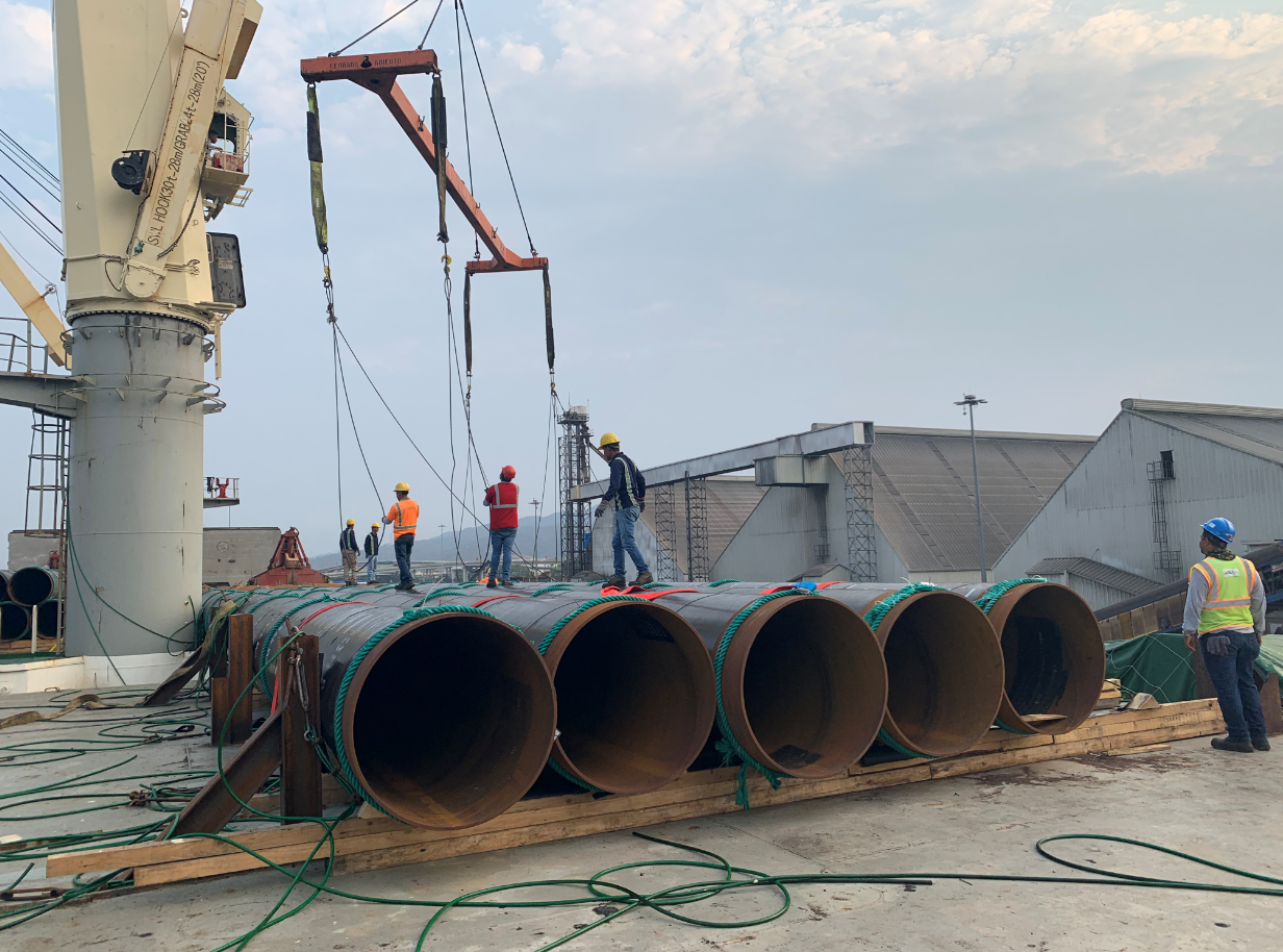
Large-diameter steel pipe piles, typically exceeding 1 meter in diameter, are foundational elements in civil engineering, supporting structures like offshore wind turbines, bridges, and high-rise buildings. Their ability to transfer heavy loads to deeper, stable soil layers or bedrock makes them indispensable in challenging geotechnical conditions. This study provides an in-depth analysis of construction methods—impact pile driving, vibratory pile driving, hydraulic pressing, and drilling-based installation—focusing on their technical mechanisms, equipment, soil interactions, environmental impacts, and cost-efficiency. Through detailed comparisons, case studies, and mathematical models, the study aims to guide engineers in selecting optimal methods for specific project requirements.
The objectives are to:
- Analyze the technical and operational aspects of each method.
- Compare performance metrics using quantitative data.
- Evaluate environmental and economic trade-offs.
- Highlight innovations and future trends in pile installation.
2. Overview of Construction Methods
Four primary methods are used to install large-diameter steel pipe piles, each suited to specific soil types, project scales, and environmental constraints:
- Impact Pile Driving: Uses high-energy hammers to drive piles into the ground, ideal for dense soils.
- Vibratory Pile Driving: Employs oscillatory forces to reduce soil friction, effective in loose sediments.
- Hydraulic Pressing: Applies static pressure to insert piles, minimizing noise and vibration.
- Drilling-Based Installation: Combines pre-drilling with pile insertion, suitable for hard or rocky soils.
Each method involves distinct equipment, installation speeds, and geotechnical considerations, necessitating a detailed examination of their applicability.
3. Detailed Analysis of Construction==(Methods)
3.1 Impact Pile Driving
3.1.1 Mechanism and Equipment
Impact pile driving delivers high-energy blows to the pile head using diesel or hydraulic hammers. The hammer’s kinetic energy overcomes soil resistance, driving the pile to the desired depth. Common equipment includes:
- Diesel Hammers: Deliver 50–200 kJ per blow, suitable for piles up to 3 m in diameter.
- Hydraulic Hammers: Offer precise control with energies up to 500 kJ, ideal for offshore applications.
The driving efficiency is governed by the Hiley formula:
P = (W_h * h * η) / (s + c/2)
Where:
- P = Ultimate pile capacity (kN)
- W_h = Hammer weight (kN)
- h = Drop height (m)
- η = Hammer efficiency (0.7–0.9)
- s = Permanent set per blow (m)
- c = Temporary compression (m)
3.1.2 Soil Interaction
Impact driving is most effective in dense, cohesive soils (e.g., clay with cohesion > 50 kPa) or granular soils with high friction angles (>30°). It struggles in very soft soils (e.g., silt with undrained shear strength < 20 kPa) due to insufficient resistance and in rocky layers due to potential pile damage.
3.1.3 Advantages
- High penetration rate (0.5–1 m/min) in suitable soils.
- Robust, widely available equipment with decades of proven use.
- Cost-effective for large-scale projects ($50–100/m).
3.1.4 Challenges
- High noise levels (>100 dB at 10 m), exceeding urban limits (e.g., 85 dB in EU regulations).
- Vibrations (peak particle velocity > 10 mm/s) risk damaging nearby structures.
- Pile head damage in hard soils requires protective caps.
3.1.5 Applications
Used in bridge foundations, offshore platforms, and industrial facilities where high axial loads (e.g., 10–20 MN) are required. Example: Hong Kong-Zhuhai-Macao Bridge used 2.5 m piles driven with 300 kJ hammers.
3.2 Vibratory Pile Driving
3.2.1 Mechanism and Equipment
Vibratory hammers generate high-frequency oscillations (10–30 Hz) to reduce soil friction, allowing the pile to sink under its weight or light pressure. Equipment includes:
- Eccentric Weight Vibrators: Produce 100–500 kN of centrifugal force.
- Hydraulic Vibrators: Offer variable frequency for soil-specific tuning.
The penetration rate depends on the dynamic force:
F_d = m * e * ω²
Where:
- F_d = Dynamic force (kN)
- m = Eccentric mass (kg)
- e = Eccentricity (m)
- ω = Angular frequency (rad/s)
3.2.2 Soil Interaction
Effective in loose, granular soils (e.g., sand with relative density < 50%) where friction is reduced by vibration-induced liquefaction. Ineffective in dense clays or gravels due to high shear strength.
3.2.3 Advantages
- Fast installation (1–2 m/min) in loose soils.
- Moderate noise (80–90 dB), lower than impact driving.
- Lower capital cost ($40–80/m) for suitable conditions.
3.2.4 Challenges
- Limited penetration in cohesive soils (e.g., clay with cohesion > 100 kPa).
- Potential for soil liquefaction, reducing lateral capacity.
- Requires soil testing to confirm applicability.
3.2.5 Applications
Ideal for coastal projects like ports and breakwaters. Example: Dubai’s Palm Jumeirah used 1.5 m piles installed with 200 kN vibratory hammers.
3.3 Hydraulic Pressing
3.3.1 Mechanism and Equipment
Hydraulic jacks apply static pressure (up to 10 MN) to push piles into the ground, often using reaction piles or anchors for counterforce. Equipment includes:
- Pressing Machines: Capacity of 500–2000 tons.
- Reaction Systems: Steel frames or adjacent piles for stability.
The pressing force must exceed the soil resistance:
F_p > Q_s + Q_b
Where:
- F_p = Pressing force (kN)
- Q_s = Skin friction resistance (kN)
- Q_b = Base resistance (kN)
3.3.2 Soil Interaction
Versatile across soil types, provided sufficient reaction force is available. Best for medium-density soils (e.g., silt with SPT N-value 10–30).
3.3.3 Advantages
- Low noise (<70 dB), compliant with urban regulations.
- Minimal vibration, protecting nearby structures.
- High precision in pile alignment (±10 mm).
3.3.4 Challenges
- Slow installation (0.1–0.3 m/min), increasing labor costs.
- High equipment costs ($100–150/m).
- Complex setup for reaction systems.
3.3.5 Applications
Suitable for urban projects like metro stations and high-rise foundations. Example: Shanghai Tower used 2 m piles pressed at 1500 tons.
3.4 Drilling-Based Installation
3.4.1 Mechanism and Equipment
Pre-drilling reduces soil resistance, followed by pile insertion and optional grouting. Equipment includes:
- Rotary Drills: Diameters up to 4 m, with torque > 300 kNm.
- Grouting Systems: Inject cement slurry for enhanced bonding.
The pile capacity is enhanced by grouting:
Q_u = Q_s + Q_b + Q_g
Where:
- Q_u = Ultimate capacity (kN)
- Q_g = Grout-soil bond strength (kN)
3.4.2 Soil Interaction
Effective in hard soils (e.g., rock with UCS > 50 MPa) or layered strata. Grouting improves skin friction by 20–50%.
3.4.3 Advantages
- Versatile for complex geologies.
- High load capacity with grouting (up to 30 MN).
- Reduced pile damage in rocky layers.
3.4.4 Challenges
- High costs ($120–200/m) due to drilling and grouting.
- Slow installation (0.2–0.5 m/min).
- Drilling waste disposal adds environmental concerns.
3.4.5 Applications
Used in offshore wind farms and deep foundations. Example: Dogger Bank Wind Farm used 3 m piles with drilled and grouted installation.
4. Comparative Analysis
The following table compares the methods across technical, economic, and environmental parameters:
| Parameter | Impact Driving | Vibratory Driving | Hydraulic Pressing | Drilling-Based |
|---|---|---|---|---|
| Soil Suitability | Dense, cohesive (clay, gravel) | Loose, granular (sand, silt) | Medium-density soils | Hard, rocky soils |
| Installation Speed (m/min) | 0.5–1.0 | 1.0–2.0 | 0.1–0.3 | 0.2–0.5 |
| Noise Level (dB at 10 m) | 100–120 | 80–90 | <70 | 80–85 |
| Vibration (PPV, mm/s) | 10–20 | 5–10 | <1 | 2–5 |
| Cost (USD/m) | 50–100 | 40–80 | 100–150 | 120–200 |
| Load Capacity (MN) | 10–20 | 5–15 | 8–18 | 15–30 |
| Environmental Impact | High (noise, vibration) | Moderate (soil disturbance) | Low | Moderate (waste) |
Analysis:
- Impact Driving: Cost-effective and robust but unsuitable for urban or ecologically sensitive areas due to noise and vibration. Best for projects prioritizing speed and budget.
- Vibratory Driving: Fastest method in loose soils, with moderate environmental impact. Limited by soil type, requiring pre-site geotechnical surveys.
- Hydraulic Pressing: Ideal for noise-sensitive urban projects, offering precision but at higher costs and slower speeds. Reaction system logistics can delay setup.
- Drilling-Based: Most versatile for hard soils, with high load capacity. High costs and waste management challenges limit its use to specialized projects.
5. Case Studies and Data Comparison
5.1 Case Study 1: Dogger Bank Offshore Wind Farm (North Sea)
Project Overview: Installation of 3 m diameter piles in a hard seabed (sandstone, UCS ~60 MPa). Drilling-based installation was chosen due to soil resistance.
Details:
- Equipment: Bauer BG50 rotary drill, 400 kNm torque.
- Depth: 40 m per pile.
- Time: 12 hours per pile (0.3 m/min).
- Cost: $180/m, including grouting.
- Challenges: Drilling waste disposal required offshore barges.
Outcome: Achieved 25 MN capacity per pile, meeting design requirements. Vibratory driving was tested but failed due to high refusal rates.
5.2 Case Study 2: Shanghai Tower Foundation (China)
Project Overview: Installation of 2 m diameter piles in a dense urban area with soft clay (Cu ~30 kPa). Hydraulic pressing was selected for low noise.
Details:
- Equipment: Giken Silent Piler, 1200-ton capacity.
- Depth: 50 m per pile.
- Time: 15 hours per pile (0.2 m/min).
- Cost: $130/m.
- Challenges: Reaction pile setup delayed by 2 days.
Outcome: Noise levels below 65 dB, compliant with urban limits. Achieved 15 MN capacity.
5.3 Case Study 3: Dubai Port Expansion
Project Overview: Installation of 1.8 m diameter piles in loose sand (relative density ~40%). Vibratory driving was used for speed.
Details:
- Equipment: ICE 416 vibratory hammer, 300 kN force.
- Depth: 30 m per pile.
- Time: 4 hours per pile (1.5 m/min).
- Cost: $60/m.
- Challenges: Temporary liquefaction reduced lateral capacity by 10%.
Outcome: Fast installation met tight project deadlines. Capacity of 10 MN sufficient for port loads.
5.4 Comparative Data
| Project | Method | Pile Diameter (m) | Depth (m) | Time (hr/pile) | Cost ($/m) | Capacity (MN) |
|---|---|---|---|---|---|---|
| Dogger Bank | Drilling-Based | 3.0 | 40 | 12 | 180 | 25 |
| Shanghai Tower | Hydraulic Pressing | 2.0 | 50 | 15 | 130 | 15 |
| Dubai Port | Vibratory Driving | 1.8 | 30 | 4 | 60 | 10 |
Analysis: Drilling-based methods excel in hard soils but are costly and slow. Hydraulic pressing balances cost and environmental compliance in urban settings. Vibratory driving is fastest and cheapest but limited to loose soils with moderate capacity needs.
6. Challenges and Innovations
6.1 Challenges
- Geological Variability: Unpredictable strata (e.g., boulders in sand) can halt driving or require method changes.
- Environmental Regulations: Stricter noise limits (e.g., 85 dB in EU) and marine mammal protections challenge impact driving.
- Cost Management: Balancing equipment rental, labor, and material costs is critical for profitability.
- Pile Damage: Hard soils can cause buckling or cracking, requiring costly repairs.
6.2 Innovations
- Noise Mitigation: Bubble curtains reduce underwater noise by 10–20 dB for offshore impact driving.
- Automated Monitoring: Sensors track pile alignment and soil resistance in real-time, improving precision by 15%.
- Hybrid Methods: Combining vibratory and drilling reduces installation time by 20% in mixed soils.
- Eco-Friendly Materials: Composite piles with recycled steel reduce carbon footprint by 10%.
7. Mathematical Modeling
To quantify method selection, a decision model can be used:
S = w_1*C + w_2*T + w_3*E + w_4*L
Where:
- S = Suitability score
- C = Cost ($/m, normalized)
- T = Installation time (m/min, normalized)
- E = Environmental impact (noise/vibration, normalized)
- L = Load capacity (MN, normalized)
- w_i = Weighting factors (e.g., 0.3, 0.2, 0.3, 0.2)
Example: For a 2 m pile in clay, hydraulic pressing may score higher due to low E, despite higher C.
The use of pipe piles in foundation construction has been a popular choice for many years. Pipe piles are used to transfer the load of a structure to a deeper, more stable layer of soil or rock.
Benefits of Pipe Trusses The use of pipe trusses in construction offers several notable advantages: Strength and Load-bearing Capacity: Pipe trusses are renowned for their high strength-to-weight ratio. The interconnected pipes distribute loads evenly, resulting in a sturdy and reliable structure. This allows for the construction of large spans without the need for excessive support columns or beams.
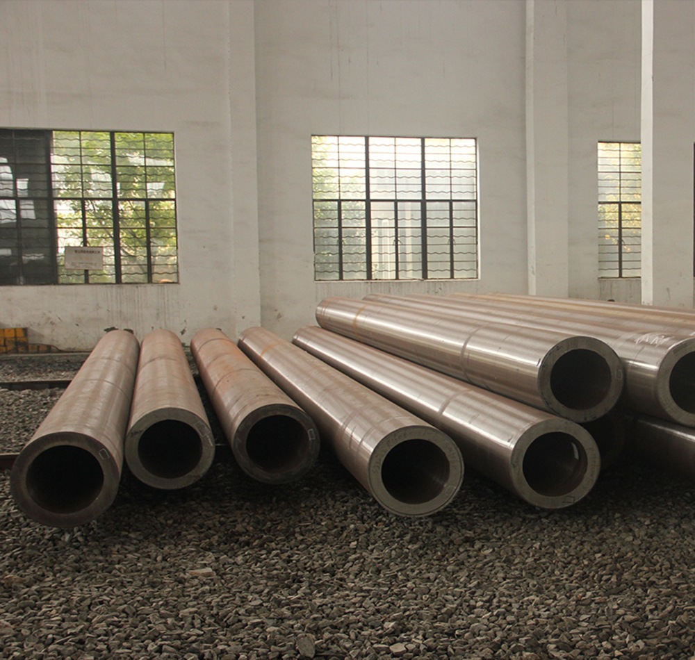
The standard for fluid-conveying seamless pipes depends on the country or region you are in, as well as the specific application. However, some widely used international standards for fluid-conveying seamless pipes are: ASTM A106: This is a standard specification for seamless carbon steel pipes for high-temperature service in the United States. It is commonly used in power plants, refineries, and other industrial applications where high temperatures and pressures are present. It covers pipes in grades A, B, and C, with varying mechanical properties depending on the grade. API 5L: This is a standard specification for line pipes used in the oil and gas industry. It covers seamless and welded steel pipes for pipeline transportation systems, including pipes for conveying gas, water, and oil. API 5L pipes are available in various grades, such as X42, X52, X60, and X65, depending on the material properties and application requirements. ASTM A53: This is a standard specification for seamless and welded black and hot-dipped galvanized steel pipes used in various industries, including fluid-conveying applications. It covers pipes in two grades, A and B, with different mechanical properties and intended uses. DIN 2448 / EN 10216: These are European standards for seamless steel pipes used in fluid-conveying applications, including water, gas, and other fluids. Read more
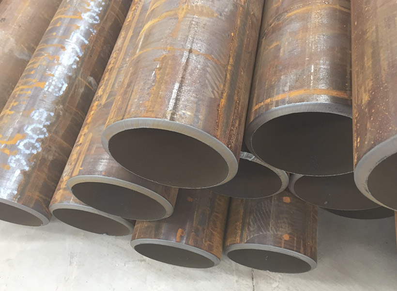
Fluid-conveying seamless pipes are designed to resist various types of corrosion depending on the material used and the specific application. Some of the most common types of corrosion that these pipes are designed to resist include: Uniform corrosion: This is the most common type of corrosion, where the entire surface of the pipe corrodes uniformly. To resist this type of corrosion, pipes are often made of corrosion-resistant materials, such as stainless steel or lined with protective coatings. Galvanic corrosion: This occurs when two dissimilar metals are in contact with each other in the presence of an electrolyte, leading to the corrosion of the more active metal. To prevent galvanic corrosion, pipes can be made of similar metals, or they can be isolated from each other using insulating materials or coatings. Pitting corrosion: Pitting is a localized form of corrosion that occurs when small areas on the pipe's surface become more susceptible to attack, leading to the formation of small pits. This type of corrosion can be prevented by using materials with high pitting resistance, such as stainless steel alloys with added molybdenum, or by applying protective coatings. Crevice corrosion: Crevice corrosion occurs in narrow spaces or gaps between two surfaces, such Read more

Wedge wire screens, also known as profile wire screens, are commonly used in various industries for their superior screening capabilities. They are constructed from triangular-shaped wire,
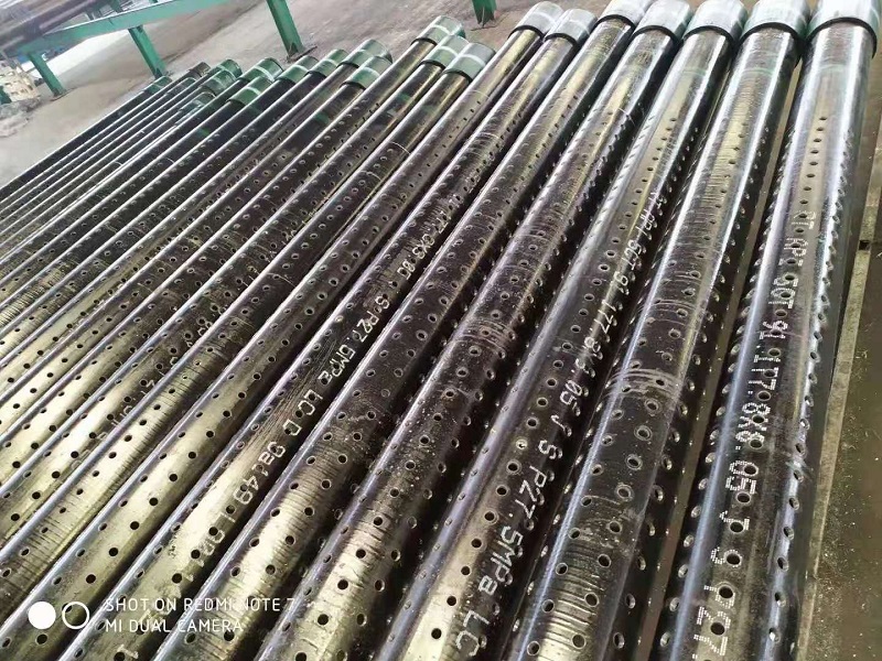
2 7/8in J55 K55 Perforated Well Casing Pipe is one of mainly products of we abter steel, they can be used for water, oil, gas well drilling fields. The thicknesss can be supplied from 5.51-11.18mm based on client's well depth and required mechanical properties. Normally they are provided with thread connection, like NUE or EUE, which will be easier to installed at site. The length of 3-12m perforated casing pipes are available for client's different drilling rigs height. The hole diameter and open area on the surface are also customized. The popular hole diameters are 9mm, 12mm, 15mm, 16mm, 19mm, etc.
