Design of Space Structures for Steel Pipe Trusses
In recent years, with the continuous growth of steel production in China, steel structures have been increasingly used in buildings due to their unique advantages. Steel pipe structures have also achieved significant breakthroughs. The greatest advantage of steel pipe structures is their ability to meet the functional, aesthetic, and economic requirements of buildings. Steel pipe truss structures are particularly favored for their unique benefits.
Design of Steel Pipe Trusses
1. Mechanical Characteristics of Pipe Truss Structures
Pipe truss structures have developed from grid structures. Compared to space truss structures, pipe truss structures have unique advantages and practicality, with relatively economical steel usage. They eliminate the need for lower chord members and ball joints found in space truss structures, making them suitable for various architectural forms, especially circular arches and arbitrary curved shapes, which are more advantageous than space truss structures. They are stable on all sides and save material consumption.
Compared to traditional open-section steel trusses (H-shaped and I-shaped steel), the cross-sectional material of pipe trusses is evenly distributed around the neutral axis, providing excellent compressive and torsional bearing capacity and greater stiffness, without the need for node plates, making the structure simple.
Importantly, pipe truss structures are aesthetically pleasing, easy to shape, and have a decorative effect. They have good overall performance, high torsional stiffness, and are relatively easy to manufacture, install, rotate, and hoist. Cold-formed thin-walled steel roof trusses are lightweight, stiff, save steel, and make full use of material strength. They are particularly economical in long slenderness ratio-controlled compression members and support systems. Currently, buildings using this structure are primarily public buildings. This structure is aesthetically pleasing (can be made flat, arched, or into any curved shape), easy to manufacture and install, structurally stable, has large roof stiffness, and good economic benefits.
2. Structural Calculation of Pipe Truss Structures
2.1 Basic Design Rules
The height of a three-dimensional truss can be 1/12 to 1/16 of the span. The arch thickness of a three-dimensional arch can be 1/20 to 1/30 of the span, and the arch height can be 1/3 to 1/6 of the span. The angle between the chord (main pipe) and the web (support pipe), and between the two webs (support pipes), should not be less than 30 degrees. For large-span three-dimensional trusses (generally not less than 30m in steel structures), camber can be considered, with the camber value not exceeding 1/300 of the truss span (generally 1/500). At this time, the internal force of the members changes little, and the design cannot be calculated using the arch. Under standard dead loads and live loads, the maximum deflection of pipe truss structures should not exceed 1/250 of the short span, and cantilevers should not exceed 1/125 of the span. The maximum deflection of roof structures with suspended hoisting equipment should not exceed 1/400 of the structural span. When only improving the appearance, the maximum deflection under standard dead loads and live loads can be taken as the deflection minus the bulging value.
2.2 General Principles of Calculation
Calculate the internal forces and displacements of pipe truss structures under gravity loads and wind loads, and calculate the displacements and internal forces under seismic, temperature changes, support settlement, and construction installation loads according to specific conditions. Using the elastic theory of space rod systems and the finite element method, the internal forces and displacements of space rod systems can be calculated. Non-seismic design should calculate the action effects and action combinations according to the current national standard “Building Structure Load Code” and determine the internal force design values according to the basic combination effects of member sections and node designs. For seismic design, the seismic combination effects should be calculated according to the current national standard “Code for Seismic Design of Buildings”. In displacement calculations, the deflection should be determined based on the combined function standard impact (without multiplying the load partial coefficient). When analyzing pipe trusses, if the ratio of the member segment length to the section height (or diameter) is less than 12 (main pipe) and 24 (support pipe), the nodes can be assumed to be hinged. According to the static equivalence principle, external loads can be concentrated on the nodes within the node control area. When a member bears local loads, the local bending stress should be considered separately. In structural analysis, the interaction between the upper space grid structure and the lower support structure should be considered.
2.3 Static Calculation
Pipe truss structures should be designed with section members through displacement and internal force calculations. If member sections need adjustment, they should be redesigned to meet design requirements. After design completion, reinforcement should not be replaced. If replacement is necessary due to material difficulties, it must be recalculated and meet the design requirements. Changes to member sections after design completion should be avoided unless absolutely necessary due to material availability issues. If changes occur, the structure must be recalculated to ensure compliance with the design requirements.
3. Design Considerations for Pipe Truss Structures
3.1 Selection of Material and Cross-Sections
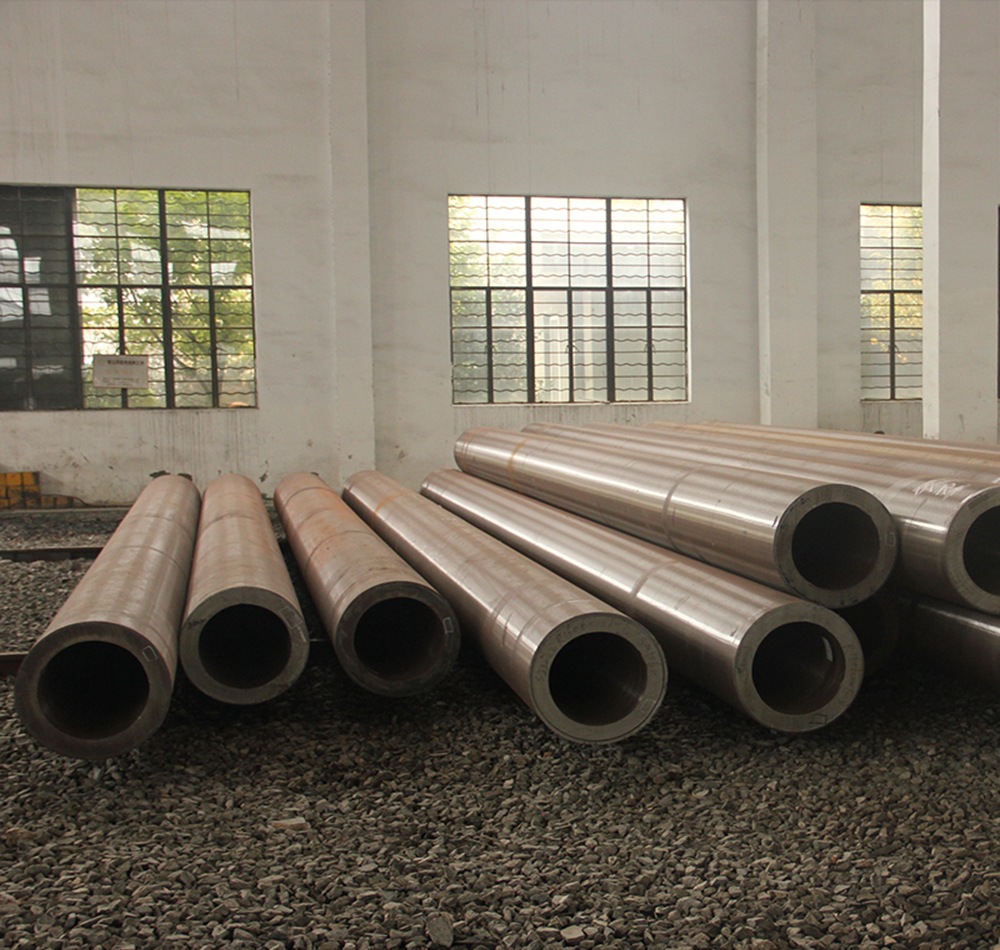
- Material Selection: The steel used in pipe truss structures should meet the requirements of relevant standards. Typically, carbon steel, low alloy steel, and high-strength steel are used. The selection should consider factors like structural requirements, environmental conditions, and economic feasibility.
- Cross-Section Selection: Circular and rectangular hollow sections are commonly used for pipe trusses due to their efficient load-carrying capacity and aesthetic appeal. The choice between circular and rectangular sections depends on the specific requirements of the project, including load conditions and architectural considerations.
3.2 Connections and Joints
- Welding: Welding is the most common method for connecting members in pipe truss structures. The welding process must ensure high-quality joints to avoid potential weak points.
- Bolted Connections: While less common in pipe trusses, bolted connections can be used in certain circumstances, especially for ease of assembly and maintenance.
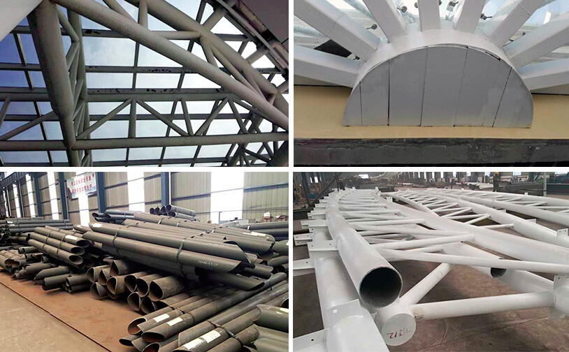
- Node Design: The design of nodes (joints where members intersect) is crucial in pipe truss structures. Nodes must be designed to transfer forces efficiently without causing undue stress concentrations.
3.3 Consideration of Dynamic Loads
- Wind Loads: Wind loads should be considered in the design of pipe truss structures, especially for large-span structures and those exposed to high wind speeds.
- Seismic Loads: In seismically active regions, the design must account for seismic loads, ensuring that the structure can withstand earthquake-induced forces.
- Vibration: For structures subjected to dynamic loads such as machinery or human activity, vibration analysis may be necessary to ensure comfort and structural integrity.
4. Construction and Erection
4.1 Fabrication
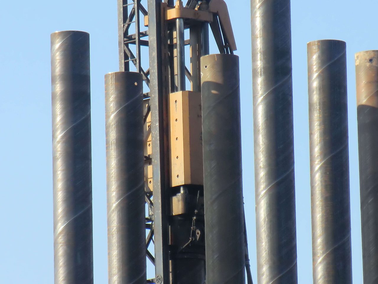
- Precision Manufacturing: Fabrication of pipe truss components requires high precision to ensure that all members fit together correctly during assembly.
- Quality Control: Rigorous quality control measures should be in place during fabrication to ensure that all components meet design specifications and standards.
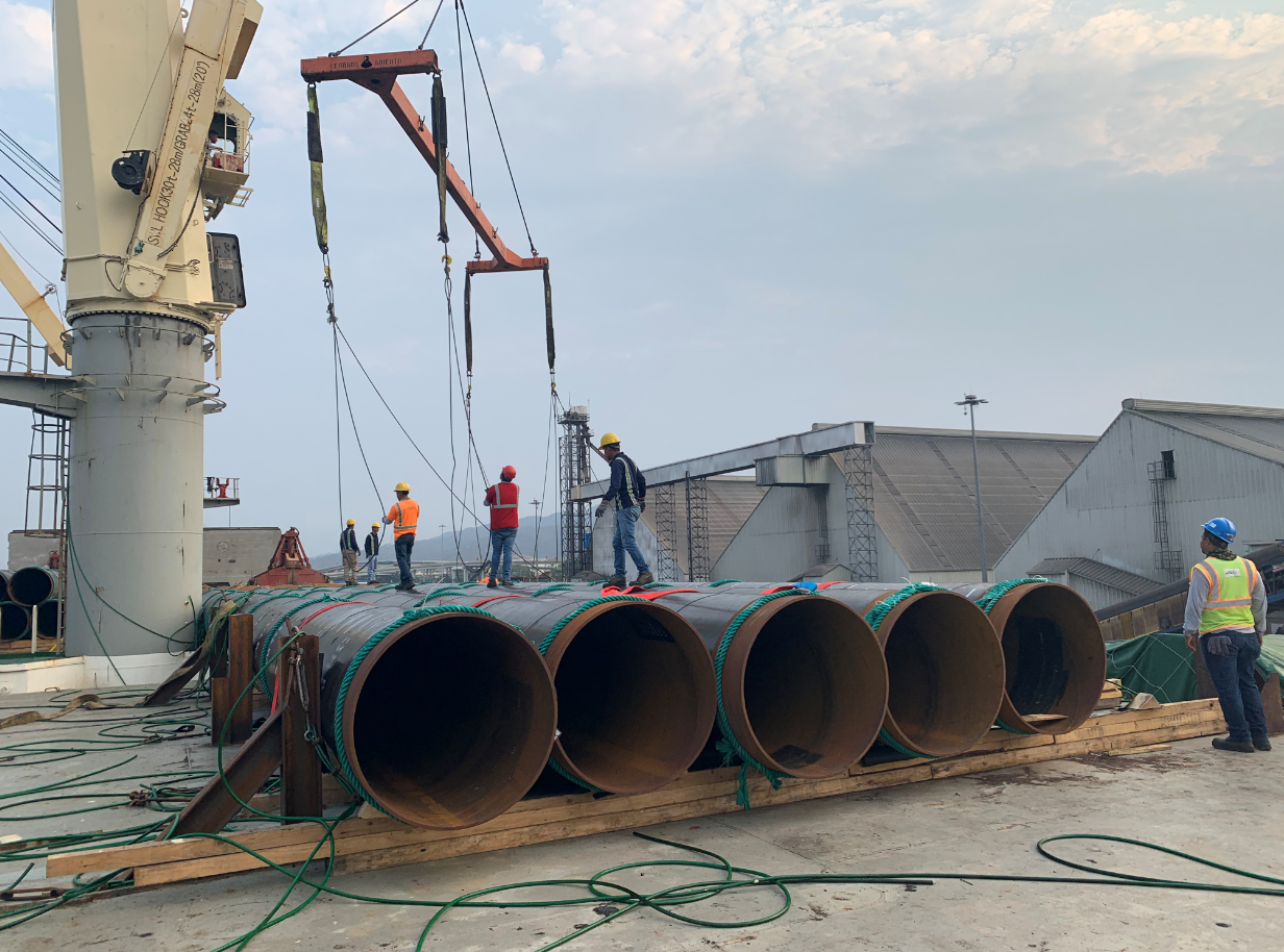
4.2 Transportation and Handling
- Transportation: The transportation of large pipe truss components must be planned carefully to avoid damage and ensure safe delivery to the construction site.
- Handling: Proper handling procedures must be followed during unloading and positioning to prevent structural damage and ensure worker safety.
4.3 Assembly and Erection
- Erection Plan: A detailed erection plan should be developed, outlining the sequence of assembly and the methods for lifting and positioning components.
- Safety Measures: Safety measures must be implemented to protect workers during the erection process, including the use of scaffolding, safety harnesses, and other protective equipment.
- Alignment and Leveling: Ensuring that all components are properly aligned and leveled during assembly is crucial for the structural integrity of the truss.
5. Maintenance and Inspection
5.1 Regular Inspections
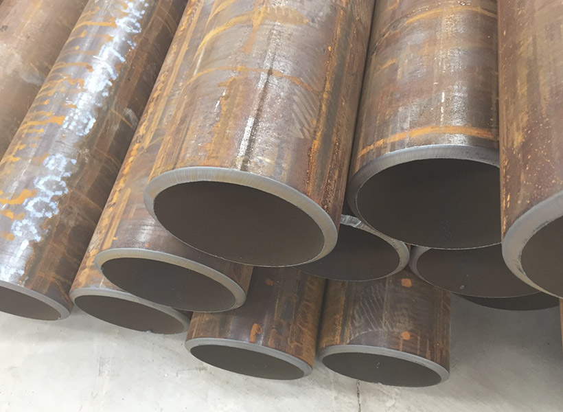
- Visual Inspections: Regular visual inspections should be conducted to check for signs of wear, corrosion, or damage.
- Non-Destructive Testing: Methods such as ultrasonic testing or radiography may be used to detect internal flaws in the members or joints.
5.2 Maintenance
- Corrosion Protection: Regular maintenance of protective coatings and other corrosion prevention measures is essential, especially for structures exposed to harsh environmental conditions.
- Repair and Reinforcement: Any detected damage should be promptly repaired, and reinforcement should be added if necessary to maintain structural integrity.
Conclusion
Steel pipe truss structures offer significant advantages in terms of aesthetics, structural performance, and material efficiency. Proper design, fabrication, erection, and maintenance are essential to fully realize these benefits. By adhering to established design principles and best practices, engineers can create durable, economical, and visually appealing pipe truss structures that meet the demands of modern architecture and construction.